This thread has been locked.

If you have a related question, please click the "Ask a related question" button in the top right corner. The newly created question will be automatically linked to this question.

ADS1120EVM: Connecting 3 and 4 Wire RTD ADCPro Settings

Part Number: ADS1120EVM
Other Parts Discussed in Thread: ADCPRO, ADS1120

Hi,

I've been using the ADS1120EVM to try to connect to ADCPro via USB however I have not found much success/made sense of the data that has been acquired by the program.

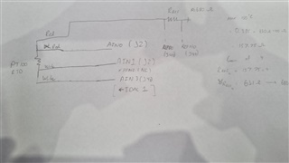
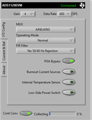
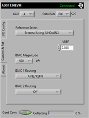
Currently I do believe it could be configuration issues with ADCPro or it could be incorrect wiring. Is there an example of someone getting a 3/4 wire RTD up and running with the EVM and ADCPro?

I can provide wiring diagrams and such if needed.

Kind regards,

Tyson

  • Hi Tyson,

    There is some connection explanation in the ADS1120EVM user's guide in section 5.2.3.  I would also suggest looking at the RTD application circuit in the ADS1120 datasheet.  There is also good information in A Basic Guide to RTD Measurements.

    Generally there is some confusion as the ADS1120 does not measure the RTD directly with a temperature.  The ADS1120 measures a value based on a voltage reference.  However, if the RTD is stimulated by the IDACs and the reference is also established by the same excitation source, the resistance can be calculated which than can be converted to a temperature.  This is explained in the documents referenced above.

    If you send me the connections you are using and the ADS1120 configuration settings I can be of more direct assistance.

    Best regards,

    Bob B

  • Hi Bob,

    Thanks for the information, I looked into the datasheet for ADS1120 to see where it should get started and there is a bit of confliction with how the 4 wire should be connected such that on the datasheet, it suggests AIN2 to not be connected however on the Basic Guide provided, it suggests using all 4 Analog inputs.

    There has not been any board modifications yet, but I am aware that some resistors such as R3 and R30 need to be added however I wasn't 100% sure whether if these modifications were needed if I used all the GPIO headers on the EVM. I used a breadboard with the bias resistor of 680 Ohms.

    The current connection diagram:

    ADCPro Configuration:

    Kind regards,

    Tyson

  • Hi Tyson,

    The minimum voltage reference value is 0.75V.  So the 500uA and 680 Ohm resistance will create a voltage that is too small for the ADC.  So you will need to increase the resistor value or set the IDAC output to 1.5mA.  Make sure that VREF- (J4-9) connects to ground so that the current path completes. 

    The MUX should be set to AIN1/AIN0, and the Reference Select should the external dedicated the REFP0/REFN0 instead of AIN0/AIN3.  The remaining connections appear to be ok.  You can check the voltages in the circuit with a DMM to make sure that the current path is complete and that the reference resistor voltage is at expected value.

    Best regards,

    Bob B

  • Hi Bob,

    Thanks again. I have measured the voltage across the Reference Resistor and has an outcome of 3.3V and achieve readings of near maximum i.e. 32767 which I don't think is correct, I will double check wiring and let you know whether I've made a mistake. Do I need to place a Reference Resistor in R3 or am I able to externally connect RRef via a breadboard? Are there any other things that need to be adjusted on the EVM board such as Jumper placement or other board modifications?

    Cheers,

    Tyson

  • Hi Tyson,

    It appears that you are missing a ground connection.  You do not need to use R3 and instead can use the header connections, but you must also provide a connection from REFN0 to ground.  This is true regardless of using the R3 resistor or the header.

    Best regards,

    Bob B

  • Hi Bob,

    Thanks for the help, there still isn't much progress in regards to determining the output of the RTD and figuring out what the voltage outputs correlate to temperature wise. The output of the sensor detected is very unstable and it is hard to know whether things are correct or it is simply measuring noise. We did a simple test by placing the RTD in boiling water and ice cold water to see variances in measurements to see if anything helped with getting a stable/polarizing reading but results were still hard to determine.

    I did connect it to a custom PCB board that has the ADS1120 controlled by a microcontroller and used SPI writing to it. The output of the ADS1120 was similar to the development board's result previously mentioned so we aren't quite sure what the issue is. We've used the ADS1120 for other applications so we are certain the chip does work (Wheatstone bridge), so it should be simply the configuration that needs more fine tuning. 

    It would be great if there was an example of someone using the ADS1120 for RTD but I haven't found much resources regarding this. Just knowing what the expected output of the ADS1120 and primarily the procedure of obtaining and extrapolating the data from the output would help us a long way. If there is an example outside of the datasheets, let me know.

    Kind regards,

    Tyson

  • Hi Tyson,

    Did you actually read and look at the circuits and description in A Basic Guide to RTD Measurements?  In addition I would suggest doing the following:

    1. Remove the RTD and use a wire short in it's place.
      1. Verify that all currents are as they should be by measuring the voltage across the VREF resistor.
      2. Make sure that the GUI is selecting the proper reference.
      3. Verify that the shorted input noise has the correct response.
    2. Next replace the short with a fixed value resistor(s).  Preferably this would a leaded precision resistor with a low temperature coefficient (low-drift).
      1. Verify that all currents are as they should be by measuring the voltage across the VREF resistor.
      2. Make sure that the GUI is selecting the proper reference.
      3. Verify that the noise does not exceed the previous test.
      4. Verify that the result resistance measurement calculates to the matching value of resistance.

    Using the shorted input give a baseline measurement of you configuration and setup.  Using a fixed value of resistance eliminates many issues with noise pickup.  I think part of the issue you are seeing is related to the antenna affect of all of the external jumper wires and leads connected.  Using the fixed values of resistance helps isolate wiring to see what issues are creating the problems and gives a baseline response. 

    There is no true analog input filtering on the ADS1120EVM, so you may need to remove some of the 0Ohm components and replace with series resistance to the ADC inputs measuring the RTD and also the reference inputs.

    Best regards,

    Bob B

  • Hi Bob,

    Thanks for your kind help, I was able to get the 4 wire RTD working with the troubleshooting methods you have provided. Noise was definitely the major issue and was circumvented by reducing the amount of wiring that was needed and referring to baseline responses from having fixed resistor values. 

    Kind regards,

    Tyson