A related question is a question created from another question. When the related question is created, it will be automatically linked to the original question.
If you have a related question, please click the "Ask a related question" button in the top right corner. The newly created question will be automatically linked to this question.
1. Pinout and connections around ADS127L11 are correct and should work with no issues.
2. The reference circuit should work well as long as the reference pre-charge buffer is enabled in each ADC. You may want to increase the capacitors from 1uF to 2.2uF to better filter the small dynamic current load presented by the ADS127L11 reference input.
3. The INA126 is a low power, low bandwidth amplifier. You will definitely need to enable the analog input pre-charge buffers in each ADC to use this amplifier. Even with the input pre-charge buffer enabled, you may not be able to support high-speed mode and maintain full ADC performance. However, the amplifier should work well if using low-speed mode. I do not have any experience using this specific amplifier with ADS127L11, so it is difficult to predict actual performance.
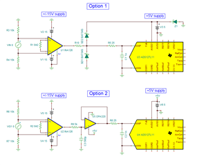
4. (Input Protection Option 1) I do not see what supply voltages are used with the INA126. If these supply voltages are greater than the ADC analog supply (less than -0.3V or greater than +5.3V), then you could exceed the ABS max rating of the ADS127L11 during power up or a fault condition. You will need to look very closely at this, since this could impact long-term reliability if these ratings are exceeded. One option is to include diode clamps on the output of the INA126 to limit the maximum voltage output.
4a. (Input Protection Option 2) Another option is to include an additional amplifier that operates from the same supply (+5V) as the ADC. The input of the amplifier can be protected with an RC filter, where the resistance limits the input current to a maximum of 10mA for a typical amplifier such as OPA2320. Also, if using a higher bandwidth amplifier such as OPA2320, it can easily drive the ADC input at the maximum operating speed.
Please refer to below drawing for a better description of the input protection options. You can also view the TI Precision Labs - ADC EOS training material that goes into more detail.