This thread has been locked.

If you have a related question, please click the "Ask a related question" button in the top right corner. The newly created question will be automatically linked to this question.

ADS1298R: Replacement and combining one ADS1298r and two ADS1299 converter

Part Number: ADS1298R
Other Parts Discussed in Thread: ADS1294, ADS1299, ADS1298, ADS1296

Hi everyone.

I have a question regarding ADS1298r analog to digital converters. We are using currently three of this chip to power out ecg equipment.
Because of chip shortages we are forced to look out for different solutions like:

1- using one ADS1298r and four ADS1294 IC-s via daisy chain

2- using one ADS1298r alongside with two ADS1299 via daisy chain

-----------------------------

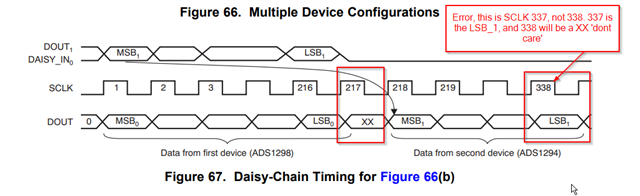
On the firs solution I have to multiply the components for the ADS1294. And then use some bit shifting to get ride of the don't care bit.
Will I have any clock issues with the SPI or other problems with this combination of ADS -es, because I read on the forum that certain number of read clock circles have to meet.
I don't have to much experience with this configuration of circuit, I'm not really able to ask good questions, for problems which might arise whit this configuration.

----------------------------

On the second solution I was thinking to replace two of the ADS1298r which is only reading analog data with the ADS1299. I didn't found to much topics on the forum regarding combining these two IC-s in a daisy chain operation, is there a reason why there are minimal topics?
Are the two IC-s different , in what part are they different is it because of the don't-care bit is not included in daisy chain operation?


Any further recommendations or topics which gives me more details on solving the arising issues would be really helpful .

Best Regards
Robert

  • Hi Robert, 

    Welcome to the E2E Design Forum. Please give us 24 hours to think it over before giving a response. 

    Kind regards,
    Nick Z

  • Hi Robert,

    It sounds like you don't need the respiration impedance signal chain on all the AFEs. In that case, I would lean you towards one ADS1298R and two ADS1298 devices. 
    However, it is certainly possible to daisy chain different ADS129x devices together. 

    The ADS1299 is a very low-noise, 8-channel AFE aimed at EEG applications, meanwhile the ADS1298 is aimed at ECG use-cases. We've also seen these devices also be daisy chained together. 

    However, we may have some other ideas in store for your application. How many ECG and respiration input channels are you in need of? What's the rough number of these systems you produce? Are there any major concerns for board space?

    Kind regards,
    Nick Z.  

  • Hi Nick,

    Thanks for your feedback. I have to brake up my feedback into parts.

    Sorry mistakenly mixed the ADS1298R and the ADS1298 part. We are using the ADS1298 without the "R" with package 64-TQFP.

    I also would like to clarify my question.

    We don’t use the respiration function; we just need to have a main ECG ADS with 8 channels which can handle the RLD and WCT functionality and the remaining two ADS they just read analog signals.

    The later we solved it with two ADS1298 which has 8 channels which means 16 channels are used totally for analog sensors.

    The way we are using these three ADS1298 chips are the following:
    We connect them together using the Daisy-chain protocol and with a Tiva TM4C1294NCPDTI3 we read all the chained data then remove the don’t-care bit then shot it of to the pc.

    I want to confirm this one:

    • "it is certainly possible to daisy chain different ADS129x devices together" - Than if we connect the ADS as following in daisy chain (ADS1298ß ADS1299ß ADS1299) will work with no issue ?

    Our main concerns are:

    1, Will it impact our PCB design ?
    2, How in which way will it impact the firmware on the MCU ?

  • What other solutions can you suggest for our application?

    • We can use 17cm x 8cm board space for the solution.
    • The Tiva TM4C1294NCPDTI3 is already at its limits, using RTOS. It is really tricky to maybe separate the ECG ADS and the analog sensor ADS-s, to read the data separately, first the ECG and then the two chained ADS-s. In this case we would also chain the two ADS1299 together.
    • Wil it require to maybe change the processor or other components?
  • Hi Robert, 

    In terms of PCB design, using 2x ADS1299 instead of 2x ADS1298 shouldn't change too much from what you're currently doing now, but due to register mappings there will be some change in configuring the device compared to the ADS1294/6/8. Please note that when I say "I've seen ADS1298 and ADS1299 chained together", it was for applications that needed both EEG and ECG. 

    Using 4x ADS1294 or 3x ADS1296, register mappings will be the same, but you'll lose a little extra PCB real estate from adding extra IC. Layout will be important; the ECG input lines are very sensitive to parasitic noise from digital or power lines running near or below them. Please see Section 12: Layout in ADS1294/6/8 datasheet for recommendations. 

    Kind regards,
    Nick Z.

  • Hi Robert, 

    I can't say much about how much it'll affect your MCU due to the level of variability with everything involved. I'll have to hold off from giving input until that system has been tested with the extra devices. 
    ADS1294/6/8 should all be similar in terms of passives and ESD protection. 

    Kind regards,
    Nick Z

  • We decided to have also a PCB configuration as follow (ADS1298 <- ADS1294 <- ADS1294 <- ADS1294 <- ADS1294 ).

    With one ADS1298 and four ADS1294. We will use 12MHz SPI clock for the ADS and a 2.048MHz clock on pin 37. This way we get the 4khz data read rate from the ADS -s

    1, Regarding the ADS1294, the unused pins the P5 and N5 til P8 and N8, should I connect it to the Ground or to VCC?

    2, Will there be any issues because of the different channel number between the two types when the data is daisy chained?

    Regards
    Robert B

  • Hi Robert, 

    Please attach unused pins to AVDD, this will help avoid any parasitic power consumption. 

    Let me double check on the data for daisy chaining and get back to you within 24 hours.

    Kind regards,
    Nick Z.  

  • Hello Robert, 

    With a ADS1298 and 4x ADS1294 setup, you probably won't experience any problems for data when daisy chaining. 
    However, please be advised there is a "don't care" bit after each ADS1294/6/8 device, so adding two more total devices (4x ADS1294 in place of 2x ADS1298) will have two more of these "dont care" bits in your ADS129x data out cycle.


    Please note that there is a slight error on the datasheet, but figure 67 is a very good demonstration of this. 

    Kind regards,
    Nick Z

  • Thanks for the help. We will get back to you when the modifications were done on the PCB and Firmware.

  • Hi Robert, 

    Good to know. I'll be closing this thread out for housekeeping, so feel free to make a fresh post whenever you have more questions. 
    Please let us know if we resolved your stated question.

    Kind regards,
    Nick Z