This thread has been locked.

If you have a related question, please click the "Ask a related question" button in the top right corner. The newly created question will be automatically linked to this question.

ADS1292R: Incorrect output Volts

Part Number: ADS1292R

Hi team,

I refer this post [How do I convert ADC output codes to volts?] and convert ADC output code to volts, and, for test signal, yes, got expected result,but got an unexpected rusult when feed a simulator signal.

Please give me some hands, thanks.

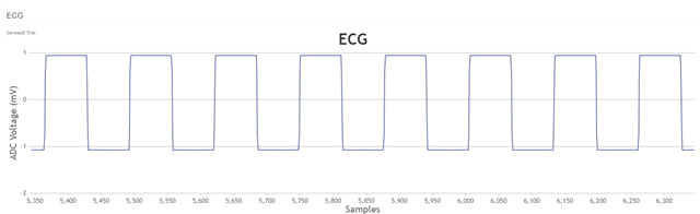
Test signal setting:

Data Rate = 125 SPS

Input signal voltage & freq: +/-1mV, 1Hz

Ouput range: -1mv ~ 1mV
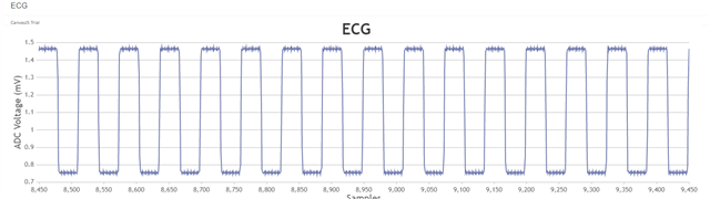
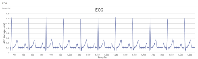
Simulator Signal:

Data Rate: 125 SPS
Input Signal voltage & seq: +/-1mV, 2Hz
Output range: 0.75mV ~ 1.75mV

for simulator signal, i have no idea if the output range should be about -1mV ~ 1mV ??

test signal@1Hz, 1mV screenshot:

simulator square signal@1mV, 2Hz:

Sq

simulator ecg signal@ 1mV:

ecg

Best regards,

Gavin

  • Hi,

      Would you please specify/clarify what you mean by got unexpected results?

      May I ask if you have/use any ADS1292R evaluation kit/board EVM?

      Are you using the built-in test signal?

      What are VREFP and VREFN? 

     What are your Vref and Gain setting?

      According to ADS1292R data sheet, amplitude should be around +- (VREFP-VREFN)/2400. 

      What might be your simulator source? Is it a function generator or a ECG simulator? And how did you connect the cables/wires to the inputs?

      I may suggest verify/validate you simulator source first and/or test the simulator signal use ADS1292R EVM to take a look.   

    Thanks

  • Hi,
    Since I did not hear back from you, I believe my suggestions answered your questions.
    I will close this post and if you have any pending questions, feel free to post them here or open a new thread.
    Thanks and have a great day!