Hello,
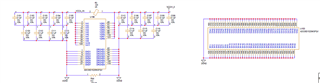
Trying to configure the ADC in Extended-Control Mode with Pin 41 set to low. As you can see in the attached image.
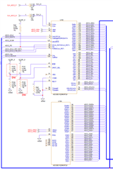
Data rate at 250msps, with CLK+/-(pin 18 and 19) set to 250MHz.
Goal is to send the data on VINI+/-(pin11 and 10) and receive data on DId0+/- thru DId7+/-
and send data on VINQ+/-(pin22 and 23) and receive data on and DQd0+/- thru DQd7+/-.
In Extended -Control Mode, while I am writing the registers
Do I have to set Pin15,26,14,and 30 to 'Z' ? Is this must ? what happens we have leave them driving.
Can please comment on my register setup for calibration for above datarate setup:
x"001" & x"1" & x"B7FF"; --Header & Reg Address & Reg Data(ConfigReg)
x"001" & x"9" & x"03FF"; --Header & Reg Address & Reg Data(ExtConfigReg)
x"001" & x"2" & x"007F"; --Header & Reg Address & Reg Data(IoffsetReg)
x"001" & x"A" & x"007F"; --Header & Reg Address & Reg Data(QoffsetReg)
x"001" & x"3" & x"E07F"; --Header & Reg Address & Reg Data(IfullscaleReg)
x"001" & x"B" & x"E07F"; --Header & Reg Address & Reg Data(QfullscaleReg)
x"001" & x"E" & x"00FF"; --Header & Reg Address & Reg Data(ClockPhasFineAdjustReg)
x"001" & x"F" & x"007F"; --Header & Reg Address & Reg Data(Int/CoarseAdjustReg)
x"001" & x"0" & x"7FFF"; --Header & Reg Address & Reg Data(CalibReg)(CAL='0')
wait for 1280 cycles and then setup the following register
x"001" & x"0" & x"FFFF"; --Header & Reg Address & Reg Data(CalibReg)(CAL='1')
One more question on Input Select Bit, it is kind of confusing. Can you please let me know whether am i setting the following bit correct for the setup I am using.
IS: Input Select. When this bit is set to 0b the I- Channel input is operated upon by both ADCs. When this bit is
set to 1b the Q- Channel input is operated on by both ADCs.
Thank you in advance.
MK