This thread has been locked.

If you have a related question, please click the "Ask a related question" button in the top right corner. The newly created question will be automatically linked to this question.

ADS8900B: Custom board for ADS 8900B

Part Number: ADS8900B

Hi,
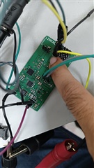
I have developed a custom board for ADS8900B, according to shared schematic.

adc_01.pdf        ref_conn_01.pdf


and following the correction provided from this thread

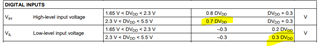
For communicating with ADC, what i understand from "data sheet" is you give a HIGH CONVST pulse and monitor for RVS pin to go up. Once RVS rising edge detected then go for SPI comm by lowering CS pin  ........

So, to do that i applied 1Khz (3.3V) signal to CONVST pin , but there is no activity in RVS pin.  PLEASE CLEAR MY UNDERSTANDING.  and SUGGEST me a proper way do SPI comm with my custom board.

regards

-------

Pratik

  • Hello Pratik,

    DVDD pin 16 is connected to the 5V supply (I assume you have this set to 5.5V so the LDO U3 can maintain an output voltage of +5.3V).  DVDD sets the IO level voltage, which must be at least 0.7*DVDD for a high level, or 3.85V (3.5V for DVDD=5V), which is not compatible with 3.3V logic.

    Either change DVDD to 3.3V, or increase the voltage from the 1kHz source to 5V logic levels.

    Regards,
    Keith Nicholas
    Precision ADC Applications

  • Thank you for your suggestion it really solved my issue.. now i am getting the RVS signal exactly as i wanted...

    But, there is another problem may be not relevant to this topic, RVS signal only comes out when I touch the board with my finger. other wise the RVS pin is mute.   

    like shown in photo. can you suggest something. (the Polygon Pour for upper and lower layer is connected to GND)

    .

    my custom board for ADS8900B

    regards

    Pratik

  • above problem is solved as i keep the CS pin high the board behaved quite normal . !