


Hi~. I have three questions
1) In the Ti site, there are two diff fc calculation equations as below. Which one is right?

2) I need to use a voltage divider resistor to lower the adc input value. If the divider resistor is in front or behind the filter circuit, or if the without an additional filter, connect the pull-down resistor in parallel to common noise filter cap Ccm to make the voltage divider and the filter together, which is more effective?
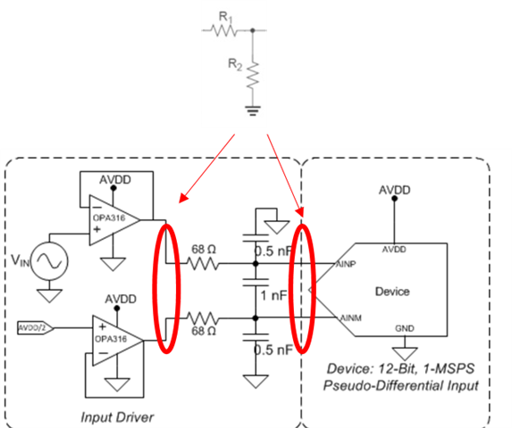
3) ) What is the reason for common mode filter when using diff adc? If common noise occurs in AINP&AINN, does it become AINP-AINN and noise is removed?
Thanks.

