This thread has been locked.

If you have a related question, please click the "Ask a related question" button in the top right corner. The newly created question will be automatically linked to this question.

ADC161S626: Vcm range

Part Number: ADC161S626

Hi team,

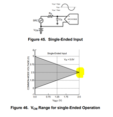
If the ADC161S626 is been driven by a singe-ended source as below shown, and when Vref=2.5V,Vcm =2.5V,  would the output of ADC161S626 be distorted?

Thank you!

Regards,
Ivy
  • Hello Ivy,

    In single ended configuration, the ADC161S626 will have slightly degraded performance verses driving the input fully differential, but the part will still perform very well.

    Per the datasheet, INL and DNL will degrade by about 0.1LSB, and the overall SINAD (and SNR) will degrade by about 2dB.

    Regards,
    Keith Nicholas
    Precision ADC Applications

  • Hi Keith,

    Thanks for your comments.

    Can I understand if the Vref=2.5V, the Vcm can't exceed 2.5V or below 2.5V, if over the Vcm range(shaded in the figure), what will the output?

    Regards,

    Ivy

  • Hello Ivy,

    The +IN analog input is limited from 0V to VA, which is typically equal to 5V.  Since the full scale input range [Vdiff=(+IN)-(-IN)] is from -Vref to +Vref, and Vref=2.5V, then the only level for -IN pin that supports the full range is -IN=Vcm=2.5V.  

    You can change the voltage on the -IN pin and this will limit the full scale input range that can be measured.

    Example 1: Vref=2.5V, Vcm=4V

    +IN=5V, Vdiff:max=(5-4)=+1V

    +IN=1.5V, Vdiff:min=(1.5-4)=-2.5V

    In this case, you will lose some of your full scale input range because the maximum differential input voltage that can be measured is +1V.

    Example 2: Vref=2.5V, Vcm=1.5V

    +IN=4V, Vdif:maxf=(4-1.5)=+2.5V

    +IN=0V, Vdiff:min=(0-1.5)=-1.5V

    In this case, you also lose some of your full scale input range because the minimum differential input voltage that can  be measured is -1.5V.

    I hope this helps!

    Regards,
    Keith

  • Hi Keith,

    Thanks for your reply.

    The common mode voltage Vcm shown in Figure 46 is not the same as the actual calculated Vcm', which I have some doubts about. Could you please help give some comments? Thank you.

    Example 1: Vref=2.5V, Vcm=4V

    -IN=Vcm=4V

    +IN max=VA=5V

    Actual Vcm'=[(-IN)+(+IN)]/2=4.5V>Vcm(4V)

    Regards,

    Ivy

  • Hello Ivy,

    Yes, this is confusing.  The datasheet is referring to the voltage applied to the (-IN) pin as the common mode voltage, which is not technically correct.

    As you pointed out, the actual definition of Vcm should be [(-IN)+(+IN)]/2, but in this older datasheet, Vcm is simply equal to the voltage applied to (-IN) pin.

    I hope this helps clear thinks up.

    Regards,
    Keith