This thread has been locked.

If you have a related question, please click the "Ask a related question" button in the top right corner. The newly created question will be automatically linked to this question.

ADS7044: ADC Data Output Issues

Genius 13919 points
Part Number: ADS7044

Hi Experts,

Seeking your assistance on this query posting on behalf of my Cx:

SETUP:

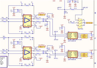
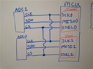
I have two analog-to-digital converters (both ADS7044IDCUR) setup for acquisition of a static, DC signal and communicating with a microcontroller.  I am trying to retrieve data from both ADCs simultaneously.  To do this, I have one SPI bus on the microcontroller configured in master mode and the other SPI bus configured in slave mode.  I then have the master's slave select and clock tied to the slave's slave select and clock.  In this way, the master can clock data from one ADC into its own RX FIFO and from the other ADC into the slave's RX FIFO simultaneously.

PROBLEM:

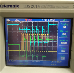
The slave's ADC is clocking out accurate data/values as expected.  However, the problem I am encountering is that the master's ADC is not clocking out proper data.  By this I am primarily referring to two issues.  First, the master's ADC is clocking out data that is very random and inconsistent (there is no noticeable pattern or general proximity of values).  Some values even have bits 12 and 13 set to 1, which is impossible according to the datasheet.  Second, the digital signal on the SDO pin of the master's ADC is malfunctioning, being caught in an intermediary voltage level between high and low at times.  I have attached a picture from an oscilloscope to illustrate this.  In the image, the yellow signal is the clock, the blue signal is the master's SDO from its ADC, and the green signal is the slave's SDO from its ADC.  As you can see from the image, the master's SDO high signal is clipped below a true 3.3V high signal, while the slave's SDO high signal reaches a true 3.3V high signal.

Do you have any idea why the master ADC would be behaving in this way?
I have verified that none of the master ADC pins are shorted together, and that the supply voltage rails for both master and slave ADCs are as expected.  My clocking frequency is ~1MHz.

Thank you.

Regards,
Archie A.

  • Hi Archie,

    Do you have a schematic available to share? I would like take a look if possible. Additionally, it sounds like 1 ADC is acting as a peripheral and the other ADC a controller, is this correct? If so, I do not believe that this ADC is capable of acting as a controller and that is what may be causing this behavior. 

    Regards,

    Aaron Estrada

  • Hello Aaron,

    Thanks for your support.

    Both ADCs are acting as SPI peripherals/slaves. Only master is a single SPI bus on the microcontroller.

    The schematic is rather complicated with multiple pages, ports to other pages, and optional switches that aren't obvious, so the Cx drawn effectively and attached a picture, as well as included a screenshot of the ADCs with the surrounding components in their schematic.

    Thank you.

    Regards,
    Archie A.

  • Hi Archie,

    Thanks for providing some clarification. So just to double check, it is ADC 1 in the whiteboard drawing that is behaving unexpectedly? Taking a look at the o-scope capture again, it definitely looks like there is some contention going on with the blue trace and that is likely why the pin is getting pulled up to an intermediary level. This is something I initially looked over but would like to state that this can be caused by the DUT trying to pull the line LOW but the MCU side trying to pull the line HIGH. 

    Can the I/O states of the master side of the MCU be verified? Ensure that SCK and CS are both set as output and MISO is set as an input. Since SCK and CS are connected between the the two peripherals, please check the states on the slave side as well to make sure that isn't the source of the contention. 

    Additionally, perhaps the customer may be able to lift the pin of the ADC (If you are using a VSSOP package) or if there is a series resistor or component  that you might be able to remove to double check the SDO/MISO lines independently. 

    Regards,
    Aaron Estrada

  • Hello Aaron,

    Cx found and fixed the problem.

    They forgot he has a third ADC on the board that shares the data and clock lines with the master. Forgot to set the chip select pin on that ADC high to disable it for now, so it was attempting to drive the data line against the first ADC. They have set that chip select pin high now to disable the third ADC, and the data coming from the first ADC is as expected now.

    Thanks for your help.

    Regards,
    Archie A.

  • Hi Archie,

    Glad the customer has found the source of the bus contention!


    Regards,
    Aaron Estrada