Other Parts Discussed in Thread: MSP430F5517,
Hi everyone!
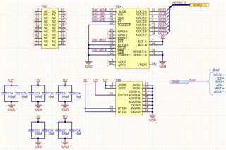
I'm using an MSP430F5517 MCU to communicate with a DAC8718 over SPI. The nCS, SCLK, MOSI, and MISO signals between the two devices appear correct on the oscilloscope:
- When a WRITE command sent over MOSI during one nCS cycle, MISO echoes all 24 bits of the WRITE command on the next cycle.
- When a READ command is sent over MOSI during one nCS cycle, MISO echoes the first 8 bits of the READ command followed by the 16-bit value of the target register on the next cycle.
However, the DAC does not produce any voltages at its outputs. When the circuit is powered, every channel produces a steady 11mV regardless of the value written to the register. The DAC operates in single-supply mode with the following rail voltages:
- IOVDD = 3.3V
- DVDD = 5V
- AVDD = 31V
- DGND = 0V
- AGND-A = 0V
- AGND-B = 0V
- AVSS = 0V
OFFSET-A and OFFSET-B are both tied to AVSS as defined by the datasheet for single-supply operation. REF-A and REF-B are both tied to a steady 5V source, and the gain bits in the configuration register are set for a gain of 6 to produce a maximum theoretical output of 30V.
The following is my setup code for the SPI engine on the MSP430:
//DAC USCI configuration
UCA1CTL1 = UCSWRST;                //unlock USCI A1 registers
UCA1CTL0 = UCMSB + UCMST + UCSYNC; //configure change on first edge, LOW idle, MSB first, 8-bit, master, 3-pin SPI, synchronous
UCA1CTL1 |= UCSSEL_1;              //configure ACLK as source for BRCLK (ACLK = 1MHz)
UCA1BR0 = 0;                       //disable prescaler
UCA1BR1 = 0;                       //disable prescaler
UCA1CTL1 &= ~UCSWRST;              //lock USCI A1 registers, initialize USCI A1 state machine
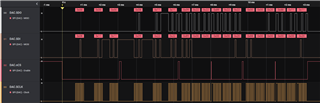
I created a test program to send commands to the DAC after initializing the MSP430 SPI engine. In order, the data packets I send and receive are detailed below:
- MOSI: 0x081111 MISO: 0x000000 (no previous command)
- MOSI: 0x092222 MISO: 0x081111 (echo of "write register 8 as 0x1111" command)
- MOSI: 0x890000 MISO: 0x092222 (echo of "write register 9 as 0x2222" command)
- MOSI: 0x000020 MISO: 0x892222 (echo of "read register 9" command, followed by value of register 9)
- MOSI: 0x880000 MISO: 0x000020 (echo of "no operation" command)
- MOSI: 0x000020 MISO: 0x881111 (echo of "read register 8" command, followed by value of register 8)
Here is a capture from the logic analyzer I'm using that shows the same data:
What could I be doing wrong?