This thread has been locked.

If you have a related question, please click the "Ask a related question" button in the top right corner. The newly created question will be automatically linked to this question.

ADS114S06: Single end input, data 0V to 3.3V with AVDD=3.3V

Part Number: ADS114S06
Other Parts Discussed in Thread: ADS124S08

HI expert, 

My customer would like to read the AD data between 0V and 3.3V 16bit(8000h0V)~ 7FFFh(3.3V))with AVDD=3.3V and single end input.

They are considering the following configration.

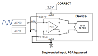
AINN=AIN1=(AVDD-AVSS)/2   

VB_LEVEL bit of VVBIAS register

Can they read the data between 0V and 3.3V(16bit) with above configuration?

Customer refered the following apps note.

https://www.ti.com/lit/an/sbaa133a/sbaa133a.pdf


Can ADS114S06 read Full scale data? 

Thanks

Muk

  • Hi Yusuke Mukuno,

    Yes, this is a valid configuration, and is called a pseudo differential input.

    Assuming that VBIAS = 1.65V in your system ((AVDD-AVSS)/2), then you should be able to measure a differential signal of +1.35V / - 1.65V. You will therefore lose some resolution on the positive code range (+FS), but it will be close to using the entire ADC code range.

    -Bryan

  • Hi Bryan Linzon86,

    thank you for answering this question.

    this is the customer,Hirotaka Ashida.
    why is "you should be able to measure a differential signal of +1.35V/ - 1.65V. "?
    especially,+1.35V.

    PGA=Bypass

  • Hi,

    If AIN1 is connected to 1.65V and you apply a 3V signal to AIN0, you will measure 3V - 1.65V = 1.35V

    If AIN1 is connected to 1.65V and you apply a 0V signal to AIN0, you will measure 0V - 1.65V = -1.65V

    So this is your measurement range

    -Bryan

  • Hi,
    thank you for my comment.

    I want to measure3.3Vsignal.

     So AIN1 is connected to 1.65V and you apply a 3.3V signal to AIN0,  I will measure 3.3V - 1.65V = 1.65V.
    this is my measurement range.

    Is it ok ?

  • Hi,

    Yes, this is correct. I misread the initial post and thought you were measuring from 0-3V

    One other issue to consider: the VBIAS source on the ADS124S08 is not a precision output and the initial accuracy is not specified. If the output voltage is not exactly 1.65V, you will lose some code range.

    For example, if the VBIAS output is 1.7V, your full scale range will be +/-1.7V, but your system will only use -1.7V to +1.6V

    If the VBIAS output is 1.6V, your full scale range will be +/-1.6V. This accommodates an input range of 0V to 3.2V. Therefore, an input voltage >3.2V will clip.

    In other words, you are theoretically able to use the entire ADC code range, but in your actual system you might see that this is not the case. It might make sense to allow some headroom between your input signals and the ADC full-scale range.

    -Bryan

  • Hi,Bryan

    I  want to set some headroom between our input signals.

    I am grateful to you for your support.

    thank you.

  • Bryan,

    Thank you for your support

  • Glad we could help, let us know if anything else is needed.

    If you do have additional questions please start a new thread and we will support you there

    -Bryan