This thread has been locked.

If you have a related question, please click the "Ask a related question" button in the top right corner. The newly created question will be automatically linked to this question.

ADS8422: COMMOUT is 0.15 volts when REFOUT is 4.1V

Part Number: ADS8422
Other Parts Discussed in Thread: THS4131, ADS8412

We are in a bit of a bind. We just produced ten boards that each use 8 ADS8422, four on the top layer and four on the bottom.

The problem is that the four ADS devices on the top layer only, output about 0.15 VDC on COMMOUT instead of the REFIN/2 specified in the datasheet. Reading a sample from the ADS produced a 0x0000 (hard zero).

The four devices on the bottom layer all output about 2 VDC from COMMOUT.

All COMMOUT pins are used on pin 2 of their respective op amps. Removing the op amp from one of the defective channels raises COMMOUT to 0.5 VDC.

REFOUT puts out about 4.1 volts (OK) and this is connected to REFIN. The device is therefore not in analog power down mode.

I checked all the other pins either with a multimeter or an oscilloscope, and they are all normal, in fact identical to the values on the bottom layer devices.

What kind of situation would cause an ADS8422 to output such a low voltage while REFOUT works fine and REFIN is connected to REFOUT?
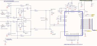
Thanks for your help.

Mike C Detaille,

Zensol Automation Inc.

  • Hello Mike,

    First, welcome to the TI E2E community.

    I have not seen this issue before.  The COMMOUT pin can only drive 200uA, so it would not take too much to pull it down.  My first thought was the THS4131 was somehow pulling the pin low, but you removed the amplifier, and the COMMOUT only measures 0.5V, so it seems that something else is causing the problem.

    • Can you confirm that pin 38, PD2, is pulled high to the VBD supply? 
    • Also, please measure the COMMOUT pin with a scope to see if there is any kind of oscillation on this pin.
    • Please verify that CAP1 and CAP2 (pins 9 and 13) are approximately 3.0V.
    • I noticed that you have two separate grounds.  Please confirm that the AGND and DGND planes are connected together near the ADC section of the board.  If not connected near the ADC package, try temporarily shorting these together near the ADS8422 and repower the board.  If the BDGND and AGND pins are driven more than 0.3V apart during power-up, this could cause part of the ADC to latch-up and not work properly.

    Regards,
    Keith Nicholas
    Precision ADC Applications

  • Hi, Keith,

    We finally found the source of the problem: the part ADS8412 (which we no longer use) was mistakenly ordered instead of the ADS8422. That was the last thing I would have checked, since the ADS8412 is ancient history for us. So all ten boards have all ADS8422 on the bottom side and all ADS8412 on the top side - save for one oddball with one 8422 and three on top,

    One of the first things I checked (before we figured it out) was PD2 and it was indeed pulled high. Just as perplexing was REFOUT which was at about 4 volts, ruling out power down mode.

    CAP1 and CAP2 were at zero.

    Finally, the two grounds you observed are tied together at the source (power supply inputs).

    This board is the latest revision and it worked fantastically with the batch of 30 we had done earlier in the year.

    Thanks for the help!

    Regards,

    Mike C Detaille
    Zensol Automation Inc.