This thread has been locked.

If you have a related question, please click the "Ask a related question" button in the top right corner. The newly created question will be automatically linked to this question.

ADS124S08: Quantifying input current on "unconnected" MUX connections

Part Number: ADS124S08

Hello,

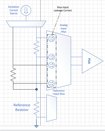
I would like to know what the input leakage is for the unconnected MUX connections. For example, I have a circuit shown below, which is copied from page 32 of the ADS124S08 datasheet: 

I notice that there are many switches and two input protection diodes which all will cause a certain amount of input leakage. I did not see the input leakage specified for these components. How can I find out their maximum current leakage for values?

Thank You,

Ethan

  • Hi Ethan,

    The leakage is included or contained in the same characteristics graphs presented in the Absolute Input Current as shown in section 7.8 figures 8 through 11.  The primary leakage occurs at the highest operating temperatures and when the inputs are near the supply extremes.  So the graphs show both input sampling and leakage.

    Best regards.

    Bob B

  • Hi Bob, 

    The leakage is specified with respect to the PGA bypassed / enabled, which leads me to believe that the input to the MUX is connected to the PGA and ADC. I am trying to determine the input leakage on the input channels not connected to the PGA and ADC.

    Thank You,

    Ethan

  • Hi Ethan,

    Yes the graphs show both cases included in a worst case graph.  Where leakage is the highest is closest to AVSS, which is both the ESD and input switches connection.  I will have to see if I have any additional data just specific to just the input network.

    Best regards,

    Bob B

  • Hi Ethan,

    Unfortunately I am not able to find any additional data than what is already shown in the datasheet graphs.  In the past the concern has been how the leakage will affect the accuracy of the measurement.  I have not seen requests that are related to strictly leakage of an used channel.  From my point of view it is difficult to understand why this is important, so any light you can shed on the reasons as to why the information is important will help us moving forward.

    As temperature increases, it is the ESD diodes that become the most leaky.  As indicated in the datasheet section 10.1.5 Unused Inputs and Outputs, "To minimize leakage currents on the analog inputs, leave unused analog and reference inputs floating, or connect the inputs to mid-supply or to AVDD. Connecting unused analog or reference inputs to AVSS is possible as well, but can yield higher leakage currents than the previously mentioned options."

    In the end, the input leakage will be no greater than what is shown in the datasheet and the leakage current will also be dependent on the voltage at the input.  If the input is equal to AVSS (AGND for a unipolar supply) then the leakage worst case would be PGA bypassed.  The PGA enabled cases are shown having an input voltage within the input range of the ADC which is why it shows as less being that the input must be equal to or greater than 0.1V and not AGND which is the worst case for leakage.

    I hope that helps.

    Best regards,

    Bob B

  • Hi Bob,

    I am asking the question because of the implication of leakage shown in the following circuit:

    The leakage current on the unconnected mux inputs are contributing to the current flowing through the Reference Resistor. This contributes to the total system error. That is why I would like to quantify the amount of leakage current.

    Thanks,

    Ethan

  • Hi Ethan,

    The internal switches are T-gate and by design have many GΩ impedance with leakage currents in pA for the diagram as you have provided.  As the RTD would be well above AGND, figure 10 would apply where the current would be not at the extremes where ESD leakage would be significant. 

    From simulation data, an open mux input worst case is less than 50pA for a typical device for leakage and this is with the input close to ground.  In the range of operation for the RTD it would be around 1.5pA.  Leakage this low would be creating an error less than the level of noise of the ADC.

    Best regards,

    Bob B