This thread has been locked.

If you have a related question, please click the "Ask a related question" button in the top right corner. The newly created question will be automatically linked to this question.

ADS1261: ADS1261 PGA startup time

Part Number: ADS1261

Dear Bryan

Please refer to my post "ADS1261: Delay time after register write" of two years ago.  The project that i'm working on at the present is slightly different in that I have one differential measurement and three single ended measurements.  As before, my procedure is nearly the same; 

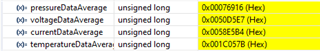
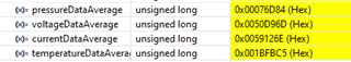
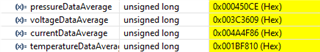
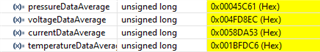
WREG(chn1(PGA,INPMUX)) ---> set START high ---> wait for DRDY ---> RDATA ---> set START low ---> WREG(chn2(PGA,INPMUX)) ---> set START high ---> wait for DRDY ---> RDATA ---> set START low ---> etc.

This process, of course, is repeated continuously.  While debugging, I noticed that chn1, the first to be sampled, logs that expected value.  However, all subsequent samples are not as before.  The PGA is set to 16 for the differential, chn1, measurement.  For the other three measurements, the PGA is set to BYPASS as required for single ended measurements.  If I put a 3.5ms delay before raising the start high, all is it should be.  It is noted in sec 9.3.2 of the data sheet, that the PGA is shut down in the BYPASS mode.  There seems to be some time required to get the PGA started and settled to the gain of 16.  Your thoughts please.  Thank you for your time. 

  • Hi Dennis McGlumphy,

    Can you help me understand what values are you getting from the ADC, and what values you are expecting? It would be helpful to see a table of values, including the input voltage, the gain setting, the VREF voltage, data rate, and the ADC output code (in hex) for each configuration.

    This will help us understand how off the measurements are compared to the desired result.

    Also, would you be willing to share a schematic? If you do not want to share your data publicly, you can hover over my name and hit "Request Friendship". This will allow us to share information via private message.

    -Bryan

  • Also, one more question: do you need to add the delay before starting each single-ended measurement? Or do you only need to add the delay once, between the differential measurement and the first single-ended measurement?

    -Bryan

  • Dear Bryan

    Please see the code snippets below.  They will show my setup and my data acquisition process.  The SPI master is running at 5MHz.

    This is in the main.

    //###################################################################
    
            if(!startPressureSample)
            {
                startPressureSample = true;
                getBridgePressureData();
                DRDYcount = 0;
    
                while(DRDYcount < nunAvg)
                {
                    ;
                }
    
                ADC_Start(LOW);     // Stop ADC
                pressureDataAverage = 0;
                startPressureSample = false;
                for(i = 0; i< nunAvg; i++)
                {
                    pressureDataAverage += ADCrawCount[i];
                }
                pressureDataAverage = pressureDataAverage / nunAvg;
                NOP;
            }
    
            //!!!!!!!!!!!!!!!!!!!!!!!!!!!!!!!!!!!!!!!!!!!!!!!!!!!!!!!!!!!
            if(!startVoltageSample)
            {
                startVoltageSample = true;
                getBridgeVoltageData();
                DRDYcount = 0;
    
                while(DRDYcount < nunAvg)
                {
                    ;
                }
    
                ADC_Start(LOW);     // Stop ADC
                voltageDataAverage = 0;
                startVoltageSample = false;
                for(i = 0; i< nunAvg; i++)
                {
                    voltageDataAverage += ADCrawCount[i];
                }
                voltageDataAverage = voltageDataAverage / nunAvg;
                NOP;
            }
    
            //!!!!!!!!!!!!!!!!!!!!!!!!!!!!!!!!!!!!!!!!!!!!!!!!!!!!!!!!!!!
            if(!startCurrentSample)
            {
                startCurrentSample = true;
                getExcitationCurrentData();
                DRDYcount = 0;
    
                while(DRDYcount < nunAvg)
                {
                    ;
                }
    
                ADC_Start(LOW);     // Stop ADC
                currentDataAverage = 0;
                startCurrentSample = false;
                for(i = 0; i< nunAvg; i++)
                {
                    currentDataAverage += ADCrawCount[i];
                }
                currentDataAverage = currentDataAverage / nunAvg;
                NOP;
            }
    
            //!!!!!!!!!!!!!!!!!!!!!!!!!!!!!!!!!!!!!!!!!!!!!!!!!!!!!!!!!!!
            if(!startTemperatureSample)
            {
                startTemperatureSample = true;
                getTemperatureData();
                DRDYcount = 0;
    
                while(DRDYcount < nunAvg)
                {
                    ;
                }
    
                ADC_Start(LOW);     // Stop ADC
                temperatureDataAverage = 0;
                startTemperatureSample = false;
                for(i = 0; i< nunAvg; i++)
                {
                    temperatureDataAverage += ADCrawCount[i];
                }
                temperatureDataAverage = temperatureDataAverage / nunAvg;
                NOP;
            }
    
    //###################################################################
    

    This is the setup.  

    //
    // This function performs the basic ADC initialization.
    //
    void ADC_init(void)
    {
        ADC_RST();          // Reset ADC
        ADC_Start(LOW);     // Stop ADC
    
        //
        // Write the MODE0 register
        // Set the sample rate to 7200SPS and the filter to SINC3.
        // (MODE0_DR_7200_SPS | MODE0_SINC3) = 0x62
        //
        ADC_Write_Reg(REG_ADDR_MODE0, (MODE0_DR_14400_SPS | MODE0_SINC1));
    
        //
        // Write the MODE1 register
        // Set the conversion start delay to 50us, chop mode to off and convertion mode to continuous.
        // (MODE1_DELAY_50_uST | MODE1_CHOP_OFF | MODE1_CONVRT_CONTINUOUS) = 0x01
        //
        ADC_Write_Reg(REG_ADDR_MODE1, (MODE1_DELAY_50_uS | MODE1_CHOP_OFF | MODE1_CONVRT_CONTINUOUS));
    
        //
        // Write the MODE2 register
        // Enables AIN2 and AIN3 as outputs.
        // Connect AIN2 to GPIO0 and AIN3 to GPIO1
        // These IOs control the bridge excitation direction switches.
        // (MODE2_GPIOCON_AIN3_ENABLE_MASK | MODE2_GPIOCON_AIN2_ENABLE_MASK) = 0x30
        //
        ADC_Write_Reg(REG_ADDR_MODE2, (MODE2_GPIOCON_AIN3_ENABLE_MASK | MODE2_GPIOCON_AIN2_ENABLE_MASK));
    
        //
        // Write the MODE3 register
        // Set AIN3's output to high. AIN2's output is default low.
        // MODE3_GPIODAT_AIN3_DATA_MASK = 0x02
        //
        ADC_Write_Reg(REG_ADDR_MODE3, MODE3_GPIODAT_AIN3_DATA_MASK);
    
        //
        // Write the REF register
        // Enable the internal reference to enable the internal current source to be used.
        // NOTE: any time the REF register is changed, REF_REFENB_MASK must be ORed with the change
        // in order to maintain the IDAC1 and IDAC21 current outputs.
        // (REF_REFENB_MASK | REF_RMUXP_INT_P | REF_RMUXN_INT_N) = 0x10
        //
        ADC_Write_Reg(REG_ADDR_REF, (REF_REFENB_MASK | REF_RMUXP_INT_P | REF_RMUXN_INT_N));
    
        //
        // Write the IMUX1 and IMUX2 registers
        // Select IDAC1 and IDAC2 to be connected to AINCOM.
        // (IMUX_IMUX2_AINCOM | IMUX_IMUX1_AINCOM) = 0xAA
        //
        ADC_Write_Reg(REG_ADDR_IMUX, (IMUX_IMUX2_AINCOM | IMUX_IMUX1_AINCOM));
    
        //
        // Write the IMAG resister
        // Set the excitation current output level.
        // (IMAG_IMAG2_100_uA | IMAG_IMAG1_250_uA) = 0x23
        //
        ADC_Write_Reg(REG_ADDR_IMAG, (IMAG_IMAG2_100_uA | IMAG_IMAG1_250_uA));
    
        DEVICE_DELAY_US(5000);    // Macro to call SysCtl_delay() to achieve a delay in microseconds.
    }
    

    These are the functions called in the main.

    //
    // This function gets the Bridge pressure data
    //
    void getBridgePressureData(void)
    {
        //
        // Write the IMUX1 and IMUX2 registers
        // Select IDAC1 and IDAC2 to be connected to AINCOM.
        // (IMUX_IMUX2_AINCOM | IMUX_IMUX1_AINCOM) = 0xAA
        //
        ADC_Write_Reg(REG_ADDR_IMUX, (IMUX_IMUX2_AINCOM | IMUX_IMUX1_AINCOM));
    
        //
        // Write the IMAG register
        // Set IDAC1 output to 100uA and IDAC2 to 250uA
        // (IMAG_IMAG2_100_uA | IMAG_IMAG1_250_uA) = 0x23
        // NOTE: The excitation current is set to 350uA to ensure that the voltage
        // at the current output pin does not exceed the 3.9V limit for a maximum
        // bridge resistance of 6350 ohm @ 50°C and the bridge voltage does not exceed
        // the 2.5V reference.
        //
        ADC_Write_Reg(REG_ADDR_IMAG, (IMAG_IMAG2_100_uA | IMAG_IMAG1_250_uA));
    
        ADC_Write_Reg(REG_ADDR_INPMUX, (INPMUX_MUXP_AIN6 | INPMUX_MUXN_AIN7));
                                        // Set the ADC inputs
                                        // (INPMUX_MUXP_AIN6 | INPMUX_MUXN_AIN7) = 0x78
    
        ADC_Write_Reg(REG_ADDR_PGA, PGA_GAIN_16);  // PGA_GAIN_16 = 0x04
    //    ADC_Write_Reg(REG_ADDR_PGA, PGA_BYPASS_MASK);  // PGA_BYPASS_MASK = 0x80
    
        DEVICE_DELAY_US(5000);    // Macro to call SysCtl_delay() to achieve a delay in microseconds.
        ADC_Start(HIGH);    // Start ADC
    
    }
    
    //
    // This function gets the Bridge supply voltage data
    //
    void getBridgeVoltageData(void)
    {
        //
        // Write the IMUX1 and IMUX2 registers
        // Select IDAC1 and IDAC2 to be connected to AINCOM.
        // (IMUX_IMUX2_AINCOM | IMUX_IMUX1_AINCOM) = 0xAA
        //
    
        //
        // Write the IMAG register
        // Set IDAC1 output to 500uA and IDAC2 to 100uA
        // (IMAG_IMAG2_100_uA | IMAG_IMAG1_250_uA) = 0x23
        // NOTE: The excitation current is set to 350uA to ensure that the voltage
        // at the current output pin does not exceed the 3.9V limit for a maximum
        // bridge resistance of 6350 ohm @ 50°C and the bridge voltage does not exceed
        // the 2.5V reference.
        //
    
        ADC_Write_Reg(REG_ADDR_INPMUX, (INPMUX_MUXP_AIN4 | INPMUX_MUXN_AIN5));
                                        // Set the ADC inputs
                                        // (INPMUX_MUXP_AIN4 | INPMUX_MUXN_AIN5) = 0x56
    
        //
        // Because this is a single ended measurement, the PGA must be by past.
        //
        ADC_Write_Reg(REG_ADDR_PGA, PGA_BYPASS_MASK);  // PGA_BYPASS_MASK = 0x80
    
    
    //    DEVICE_DELAY_US(5000);    // Macro to call SysCtl_delay() to achieve a delay in microseconds.
        ADC_Start(HIGH);    // Start ADC
    
    }
    
    //
    // This function gets the excitation current data
    //
    void getExcitationCurrentData(void)
    {
        //
        // Write the IMUX1 and IMUX2 registers
        // Select IDAC1 and IDAC2 to be connected to AINCOM.
        // (IMUX_IMUX2_AINCOM | IMUX_IMUX1_AINCOM) = 0xAA
        //
    
        //
        // Write the IMAG register
        // Set IDAC1 output to 500uA and IDAC2 to 100uA
        // (IMAG_IMAG2_100_uA | IMAG_IMAG1_250_uA) = 0x23
        // NOTE: The excitation current is set to 600uA to ensure that the voltage
        // at the current output pin does not exceed the 3.9V limit for a maximum
        // bridge resistance of 6350 ohm @ 50°C and the bridge voltage does not exceed
        // the 2.5V reference.
        //
    
        ADC_Write_Reg(REG_ADDR_INPMUX, (INPMUX_MUXP_AIN0 | INPMUX_MUXN_AIN1));
                                        // Set the ADC inputs
                                        // (INPMUX_MUXP_AIN0 | INPMUX_MUXN_AIN1) = 0x12
    
        //
        // Because this is a single ended measurement, the PGA must be by past.
        //
        ADC_Write_Reg(REG_ADDR_PGA, PGA_BYPASS_MASK);  // PGA_BYPASS_MASK = 0x80
    
    
    //    DEVICE_DELAY_US(5000);    // Macro to call SysCtl_delay() to achieve a delay in microseconds.
        ADC_Start(HIGH);    // Start ADC
    
    }
    
    //
    // This function gets the excitation current data
    //
    void getTemperatureData(void)
    {
        //
        // Write the IMUX1 and IMUX2 registers
        // Select IDAC1 to be connected to AIN8.
        // (IMUX_IMUX2_NOCONNECT | IMUX_IMUX1_AIN8) = 0xF8
        //
        ADC_Write_Reg(REG_ADDR_IMUX, (IMUX_IMUX2_NOCONNECT | IMUX_IMUX1_AIN8));
    
        //
        // Write the IMAG register
        // Set IDAC1 output to 500uA
        // (IMAG_IMAG2_OFF | IMAG_IMAG1_500_uA) = 0x04
        //
        ADC_Write_Reg(REG_ADDR_IMAG, (IMAG_IMAG2_OFF | IMAG_IMAG1_500_uA));
    
        ADC_Write_Reg(REG_ADDR_INPMUX, (INPMUX_MUXP_AIN9 | INPMUX_MUXN_AIN1));
                                        // Set the ADC inputs
                                        // (INPMUX_MUXP_AIN9 | INPMUX_MUXN_AIN1) = 0xA2
    
    
        //
        // Because this is a single ended measurement, the PGA must be by past.
        //
        ADC_Write_Reg(REG_ADDR_PGA, PGA_BYPASS_MASK);  // PGA_BYPASS_MASK = 0x80
    
    
    //    DEVICE_DELAY_US(5000);    // Macro to call SysCtl_delay() to achieve a delay in microseconds.
        ADC_Start(HIGH);    // Start ADC
    
    }
    

    This is good data and all subsequent data are good.  This was captured using the 5ms delay in the "void getBridgePressureData(void)" function.  I've done calculations to see if these data are reasonable.  Given the reported pressure at the airport and temperature measured in the lab, these numbers are very close.  Each measurement is an average of five data samples taken under ISR control.  

    This is the first pass through without the 5ms delay.  The pressure data, which is the differential measurement with a gain of 16, is as expected. 

    This represents the second and all subsequent measurements.

    NOTE: When I place the 5ms delay in the "void getBridgeVoltageData(void)" function, the following measurements are good.  

    10mm_Top-Hat_Alternate schematic rev2 6-6-2022.pdf

  • Hi Dennis McGlumphy,

    Thanks for sending over this information, some questions and comments:

    1. Can you send the raw ADC codes you receive from the ADC, instead of the averaged data? You can send all 5 data samples you collect for each measurement. Please include both the good and the bad measurements so I can see how the data changes as you collect samples. You appear to be sampling very fast (14kSPS), so I wouldn't expect a huge difference in each set of 5 samples, but it will be good to double check. I also want to understand how far off the bad data is from the good
    2. To confirm: you are not enabling the bridge chop for the differential pressure measurement, correct? I didn't see you toggling the GPIOs in the function call, but I just wanted to confirm
    3. You are using the internal VREF for all measurements?
    4. Your previous post said you were using 3.5ms for the delay, while the code you sent shows 5ms. Have you tried reducing the delay to see where the cutoff is between good and bad data? 
    5. Have you tried using the DELAY bits in the MODE1 register instead of using the delay function call? I wonder if this will produce different results
    6. I see that you are only calling the 5ms delay function in getBridgePressureData(void). This line of code appears to be commented out in the other functions. Is this the configuration that produces the errors, or does this configuration work correctly?
    7. Any reason you are using current excitation for the bridge instead of voltage excitation? Just curious...

    I can look into this in more detail once I get your responses. Nothing from the schematic or code looks wrong, at least at first glance.

    -Bryan

  • Dear Bryan

    As this is late Friday for me, I get here at 6:00 am.  I'll get back to you on Monday.  However, I can answer some things now.  

    To confirm: you are not enabling the bridge chop for the differential pressure measurement, correct? I didn't see you toggling the GPIOs in the function call, but I just wanted to confirm

    No, I'm not using the CHOP mode. I have to deliver a lot of data every 1ms.  However, if I'm able to make my code more efficient and run faster, I would like to use the AC excitation mode.  It would greatly reduce that noise level.

    You are using the internal VREF for all measurements?

    Yes, I'm using the internal 2.5v reference as my measurement reference.  I would've like to use the 5V power supply as my measurement reference but it's too noisy.

    Your previous post said you were using 3.5ms for the delay, while the code you sent shows 5ms. Have you tried reducing the delay to see where the cutoff is between good and bad data? 

    Yes, the cutoff delay time seems to be 3.5ms.  I'm using 5ms in this example to be sure everything is stable.

    I see that you are only calling the 5ms delay function in getBridgePressureData(void). This line of code appears to be commented out in the other functions. Is this the configuration that produces the errors, or does this configuration work correctly?

    This is the configuration that works.  The other 5ms delays in the other functions are there for convenience so I can switch things around easily.

    Any reason you are using current excitation for the bridge instead of voltage excitation? Just curious...

    I have two PCAs, one is constant current and the other is constant voltage.  I've done this because some pressure manufactures specify constant current while others specify constant voltage.  I'm designing for multiple vendors.  My particular belief is that a constant voltage is the way to go.  Your thoughts on this matter are welcome.

  • Thanks for the quick feedback, Dennis.

    Let me know about the raw ADC data whenever you can.

    -Bryan

  • Dear Bryan

    Please see raw data below.  


    The above data was taken with the 5ms delay.


    sample 1                                        sample 2                                       sample 3

    The above data was taken without the 5ms delay.


    The above data was taken with the 3.5ms delay.


    The above data was taken with the 4.49ms delay that was set in the ADC,s MODE1 register.  This time delay was set in the "void getBridgePressureData(void)" function only and then reset back to 50us in the following "void getBridgeVoltageData(void)" function.  The order of the function calls are as follows:

    void getBridgePressureData(void)

    void getBridgeVoltageData(void)

    void getExcitationCurrentData(void)

    void getTemperatureData(void)

    The excitation current for the first three functions is 350uA with the output at AINCOM.  The temperature function changes the excitation current to 500uA and the output to AIN8.  I still think there is some settling time required when changing the excitation current and its output.  However, having said that, I put a 5ms delay in the temperature function and saw no difference.  I would've thought there should be a difference.  The RTD is about 1100 ohm at temperature where the bridge is 4500 ohm.  The bridge is, of course, a semiconductor bridge and more than likely doesn't behave in a purely resistive manner.  In addition, the antialias filter has a step response of about 6ms according to the SPICE simulation, please see below.  Your thoughts please.  

  • Hi Dennis,

    Thanks for sending this over, the different data sets really help

    Some observations:

    • If I look at the data that is taken without the 5 ms delay (labeled "Sample 1", "Sample 2" and "Sample 3"), it looks like the temperature data is correct for all three samples relative to the data with the 5 ms (let me know if you disagree)
    • The pressure, voltage, and current data is incorrect for samples #2 and #3, but is correct for sample #1
    • The pressure, voltage, and current data for samples #2 and #3 appears to be increasing as the array index increases i.e. voltageData[1] > voltageData[0], voltageData[2] > voltageData[1], and so on. However, in this case, the data never reaches a steady state, nor does it come close to the value seen when the 5 ms delay is included
    • I also noticed that you change both IDACs for the temperature measurement, then revert them back to powering the bridge after the temperature measurements are complete

    Taking all of these observations together, it would seem there is some sort of settling issue with removing the current excitation from the bridge. As you mentioned, the bridge is not purely resistive, so it could be the bridge itself. Or, perhaps it is the anti-aliasing filter, which as you also mentioned has a settling time of ~6ms.

    To check what effect these issues have on your circuit, you can reduce the size of the differential capacitor from 100nF to something smaller e.g. 10nF. If the anti-aliasing filter is causing settling issues, this should reduce the effect.

    You might also consider leaving both IDACs on all the time, and use IDAC1 for the bridge and IDAC2 for the RTD. You will not be able to get 350uA output current if you only use 1x IDAC for the bridge, but it seems possible that 250uA or 500uA could work for your system. Choosing this approach eliminates any anti-aliasing filter settling issues because the bridge will always be powered, even when not being measured. Even if this is not the final configuration you choose for your system, it would be worth testing just to see the result

    Let me know if you are able to try these solutions, as well as the outcome of each

    -Bryan

  • Dear Bryan

    To check what effect these issues have on your circuit, you can reduce the size of the differential capacitor from 100nF to something smaller e.g. 10nF. If the anti-aliasing filter is causing settling issues, this should reduce the effect.

    I think I'll try that.  However, that will take some time because I'll have to send the PCA out for rework.  Normally I would do this myself, but the parts are all 0201 chip capacitors and I'm too old and shaky to this sort of work any longer.  

    You might also consider leaving both IDACs on all the time, and use IDAC1 for the bridge and IDAC2 for the RTD. You will not be able to get 350uA output current if you only use 1x IDAC for the bridge, but it seems possible that 250uA or 500uA could work for your system. Choosing this approach eliminates any anti-aliasing filter settling issues because the bridge will always be powered, even when not being measured. Even if this is not the final configuration you choose for your system, it would be worth testing just to see the result

    I tried this and it worked.  I'm limited to 350uA to the bridge due to ADC input bounds.  So I kept IDAC1, at output AINCOM and 250uA for the bridge at all times and switched IDAC2 between outputs AINCOM at 100uA  for the bridge and AIN8 at 500uA for the RTD.  I still have to have a 1ms delay.  However, this is acceptable.  This also gives me a better understanding of what is going on.  Great suggestion.  Thank you.  

  • Hi Dennis,

    I am glad our support enabled you to take the appropriate steps to resolve your issue

    If you have any further queries, please let me know.

    -Bryan