This thread has been locked.

If you have a related question, please click the "Ask a related question" button in the top right corner. The newly created question will be automatically linked to this question.

DAC5571: DAC5571 related issues

Part Number: DAC5571

Hello,

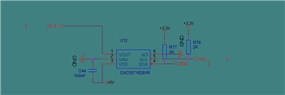
1. Please help to see if the schematic diagram of the accessories is reasonably designed?

2. After the DAC5571 is connected to the load for a period of time, the IIC cannot communicate normally. Please help analyze the possible causes.

3. What is the load capacity of DAC5571?

Thanks!

  • Hi,

    1. This schematic looks reasonable and I see no issues.

    2. Please add more detail.  What fails? What is the failure behavior? Can you confirm that the I2C frame is correctly formatted and share oscilloscope captures? Are you able to read from the device? Can you confirm the VDD supply during the failure event?

    3. The maximum capacitive load is 1nF and we specify ~20mA of short circuit current capability.

    Thanks,

    Paul

  • The IIC communication high level in the manual requires more than 3.5V. If 3.3V is used for pull-up power, will there be any problem?

  • Hi,

    If the controller is running with a 5V supply, then the I2C communications must be pulled up to 0.7*5V.

    However, if the controller is running with a 3.3V supply then the pullup should be set to 3.3V. The controller and the target device should be the same. 

    Incidentally, there is a new application note on A Basic Guide to I2C. If you have more questions about the I2C protocol, you can find the application note here:

    https://www.ti.com/lit/pdf/sbaa565

    Section 6.4 talks a little about mismatched voltages in I2C communication.

    Joseph Wu