This thread has been locked.

If you have a related question, please click the "Ask a related question" button in the top right corner. The newly created question will be automatically linked to this question.

ADS131A02: Design ADS131M02

Part Number: ADS131A02
Other Parts Discussed in Thread: ADS131M02

Hi Team,

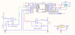
I have some concerns and need you to check when I design ADS131M02 ADC socket.

  1. Can pin 11 SYNC/RESET not connecting to the MCU, just use RC reset at power on?
  2. Can pin 13 DRDY not connecting to the MCU and how should it be designed?
  3. Whether the AIN_P can measure a negative voltage signal with the AIN_N signal grounded?

  • Hi Kevin,

    You mentioned two ADC part numbers, I assume that you are talking about ADS131M02. Please see the following feedback regarding your questions:

    1. You can simply tie the RESETn pin high (or with an RC filter), please see an example circuit in the “Minimum Interface Connections” section in the ADS131M02 datasheet.
    2. Yes, you can blindly read data from the ADS131M02 without monitoring the DRDYn signal. You will not know then if you read old data again or new data. However the device also provides a DRDY status bits for each ADC that you can check to see if new data are available.
    3. Your configuration is fine. Either of the analog inputs can swing below GND.

    BTW:  Your schematic shows that CSn is tied to high. That will not work.

    Best regards,

    Dale