Hi Team,
I am working with your ADS131E08S and have some questions on the device below.
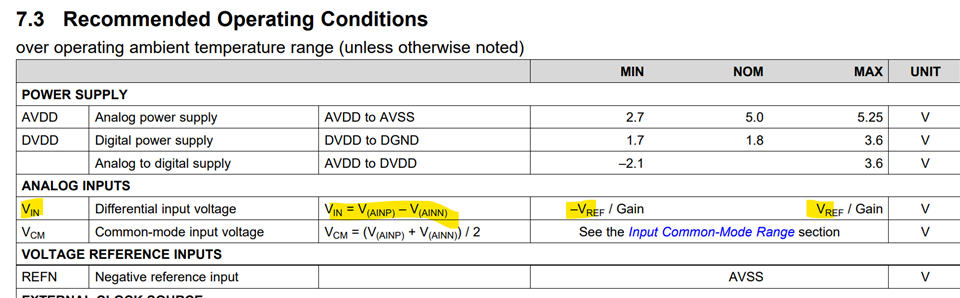
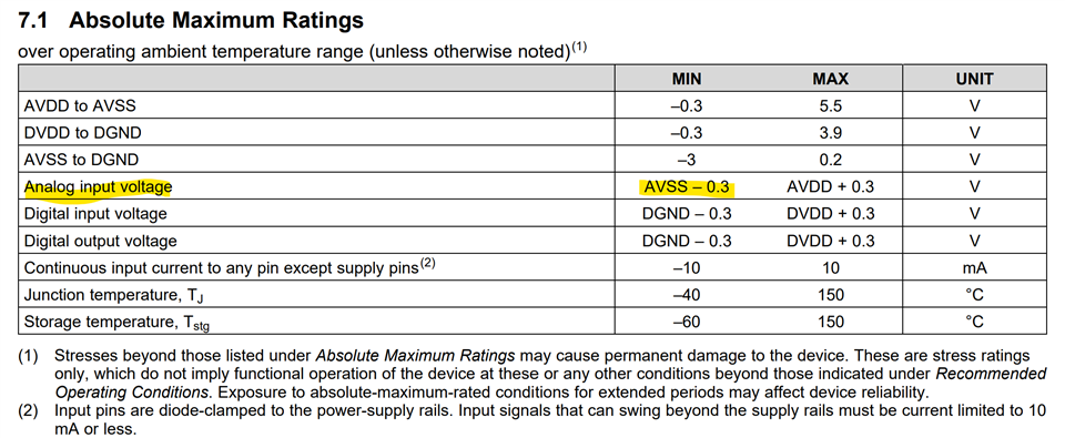
1) Are the differential inputs on these devices bipolar?
2) If so, can the device be configured to have the negative differential input grounded while the positive differential input swings between -2.5V and +2.5V?
3) If #2 is possible, do the PGA and ADC have rail-to-rail performance where the device can properly resolve signals across this entire [-2.5V to +2.5V] span if provided with -2.5V and +2.5V analog supplies?
Thanks!
Connor