This thread has been locked.

If you have a related question, please click the "Ask a related question" button in the top right corner. The newly created question will be automatically linked to this question.

ADS131M06: Programming SPI via Python

Part Number: ADS131M06

Greetings,

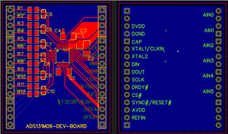
i'm currently in getting used to my first SPI-ADC for my Thesis.

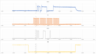
The Problem i bumbed into is that i'm able to send and receive messages to the ADC but i can not locate how much data per received Message is send. Also i'm not able to get the information on which bits of the received message which data is coming in. The Datasheet says in the chapter "Typical communication frame" that there is a Frame where always the Data from the analog-channels is send and the following answer from the rreg command. Here is where my Problem kicks in. How can i get the quantity of bit's per message out of the datasheet to receive "everything" in the next message.

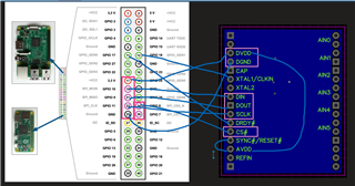
For context i'm waiting for the !DRDY Pin before i receive and send data. My MCU is a RaspberryPi 3B+ and the Masterlclock is given with 2048000 Hz from a PWM-Pin from it. I'm using the SPIDEV library to accumulate the communication frames.

Help would be really appreciated, open source forums where not really helpful and i'm stuck on this problem for like 2 weeks.

Thanks in advance,

C. Naumer

  • Hi Christian,

    I'm not sure if I have fully understood your question. I guess the "message" you are talking is actually a frame which starts at the falling edge of /CS and ends at the rising edge of /CS. You want to know how much data in a frame which are sent by the ADC, also you want to know where your conversion data start in a frame or which bits are the conversion data, please correct me if my understanding is incorrect.

    Can you please show me the timing you have captured including /CS, SCLK, DIN and DOUT? Also, please let me know your word size which is configurable by programming the WLENGTH[1:0] bits in the MODE register, and also if you have enabled input CRC. Thanks.

    Best regards,

    Dale

  • Hey Dale,

    you are understanding quite right. I'm looking for the construction of a Dataframe, so i can get the analog data out the spi "messages". I'm not sure if i'm testing correctly with my little program. I did not manipulate any of the registers (i only try to read them) and so it's like factory setting. As far as i know it excludes CRC and the word size should be 24 bit long?

    Heres a view of the timing diagram i measured with my Oszilloscope:

    Furthermore i'm unsure about if i have to do a startup kinda thing. I read about reading the registers of the analog data 2 times to clear them after a measurement pause or a startup. Because i'm programming in python with the library "SPIdev" i thought that reading the registers 2 time means, i read two messages by sending NULL and then send a rreg command to read than again. My program for this looks like this:

    #imports
    import time
    import spidev
    import RPi.GPIO as GPIO
    
    # clk is a mini class to generate a Master-Clock signal over a PWM Pin
    import clk as clk
    
    #includes all Commands for the ADS131M06
    #and also a function which gets two hex numbers and gives back the "Message" for send
    from ADS131_Command import *
    
    adcC = ADS131_Command()
    
    #settings
    GPIO.setmode(GPIO.BCM)
    GPIO.setup(17, GPIO.IN, pull_up_down=GPIO.PUD_UP)
    GPIO.add_event_detect(17,GPIO.FALLING)
    
    spi = spidev.SpiDev()
    
    spi.open(0,0) 
    spi.mode = 0b01
    spi.max_speed_hz = 2048000
    spi.lsbfirst = False
    
    def send(msg):
        while True:
            if GPIO.event_detected(17):
                #print("send some Data")
                spi.writebytes(msg)
                break
        
    def receive(n):
        while True:
            if GPIO.event_detected(17):
                #print("receive some Data")
                respbin= 0
                resp = spi.readbytes(n)
                
                for i in resp:
                    respbin = respbin<<8
                    respbin = respbin+i
                        
                print(bin(respbin))
                break
            
    if __name__ == '__main__':
        clk.clock_en(True)
        send([0b1010, 0b0001])
        receive(24)
        spi.close()
        clk.clock_en(False)

    I got a hint about programming the "first-time-use"-Frame, but i did not try to get it run. At the moment the complexity is still overwhelming.

    Thanks for your help in advance.

  • Hi Christian,

    Thank you for providing more information.

    Yes, the word size is 24-bit and the CRC on the ADC input is disabled by default, however the output CRC always appears at the end of the output frame and it can not be disabled. Your microcontroller can ignore the data if the output CRC is not used. In a frame, you should be able to see a status register data at the beginning if you did not read or write register in the previous frame, followed by 4-ch conversion data plus a word for CRC, so you need total 192 SCLKs (24+24+24+24+24+24+24+24) in a frame. Right now, you are only sending 4 bytes=32 SCLKs in a frame. 

    Lastly, I guess you were talking about "collecting data for the first time or after a pause in data collection". You can use one of two methods which are introduced in the section 8.5.1.9.1 in the datasheet.to clear FIFO and realign the ADC output with your host controller. You can use /SYNC/RSTn pin if your controller is controlling this pin or you can read data twice instead of using /SYNC/RSTn pin.

    Best regards,

    Dale