Other Parts Discussed in Thread: REF5025,
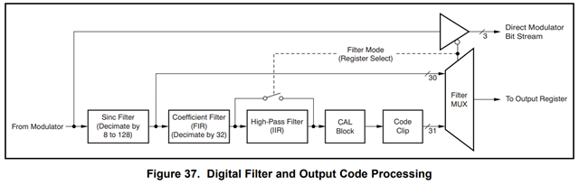
I am having trouble calculating the input voltage to the ADS1282. I am using a REF5025 as a voltage reference.
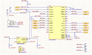
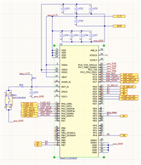
The ADS1282 is connected to a TI TIva TM4C1231D5PMT MCU.
The voltage on the input of the ADS1282 is approximately 0.5V.
I am getting the following reading on DOUT,
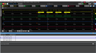
The data is read from the adc by the MCU using the adc_read() function,
int read_adc() {
unsigned int adc[6];
//0. Toggle the chip select line low (active low).
//ROM_GPIOPinWrite(GPIO_PORTD_BASE, GPIO_PIN_3, 0);
//ads1282_rdata();
adc[0] = rx_spi0();
adc[1] = rx_spi0();
adc[2] = rx_spi0();
adc[3] = rx_spi0();
//1. Toggle the chip select line low (active low).
//ROM_GPIOPinWrite(GPIO_PORTD_BASE, GPIO_PIN_3, GPIO_PIN_3);
int data = adc[0] << 24 | adc[1] << 16 | adc[2] << 8 | adc[3];
unsigned char pol_bit = data >> 31;
if (pol_bit == 0)
{
return data;
}
else
{
data = data - 1;
data = ~data;
data = -1*data;
return data;
}
}
The adc reading (data) is send to a computer through uart.
if (CH > 0){
//usprintf(&status, ">-%d<", abs(data));
status[0] = '>';
status[1] = '-';
status[2] = abs(data) >> 24;
status[3] = abs(data) >> 16;
status[4] = abs(data) >> 8;
status[5] = abs(data) >> 0;
status[6] = '<';
}
else {
//usprintf(&status, ">+%d<", abs(data));
status[0] = '>';
status[1] = '+';
status[2] = abs(data) >> 24;
status[3] = abs(data) >> 16;
status[4] = abs(data) >> 8;
status[5] = abs(data) >> 0;
status[6] = '<';
}
UARTSend(status, 7);
The ADC data is put back together in a c# program,
public int adc_count()
{
port.Write("M");
byte[] adc_count_byte = new byte[7];
System.Threading.Thread.Sleep(1);
port.Read(adc_count_byte, 0, 7);
string result = System.Text.Encoding.UTF8.GetString(adc_count_byte);
//Trace.WriteLine(result);
int adc_count = 0;
if (adc_count_byte[1] == '-')
{
adc_count = -1 *( adc_count_byte[2] << 24 | adc_count_byte[3] << 16 | adc_count_byte[4] << 8 | adc_count_byte[5]);
Trace.WriteLine($"-ADC COUNT -> {adc_count}");
Trace.WriteLine($"adc_count_byte[2] = {adc_count_byte[2]}");
Trace.WriteLine($"adc_count_byte[3] = {adc_count_byte[3]}");
Trace.WriteLine($"adc_count_byte[4] = {adc_count_byte[4]}");
Trace.WriteLine($"adc_count_byte[5] = {adc_count_byte[5]}");
}
if (adc_count_byte[1] == '+')
{
adc_count = adc_count_byte[2] << 24 | adc_count_byte[3] << 16 | adc_count_byte[4] << 8 | adc_count_byte[5];
Trace.WriteLine($"+ADC COUNT -> {adc_count}");
Trace.WriteLine($"adc_count_byte[2] = {adc_count_byte[2]}");
Trace.WriteLine($"adc_count_byte[3] = {adc_count_byte[3]}");
Trace.WriteLine($"adc_count_byte[4] = {adc_count_byte[4]}");
Trace.WriteLine($"adc_count_byte[5] = {adc_count_byte[5]}");
}
return adc_count;
}
The ADC voltage is calculated by,
public double adc_volage()
{
int adc_c = adc_count();
double voltage = (double)(adc_c * 2.5 / Math.Pow(2, 30));
//double voltage = (double)(adc_c * 2.328e-9);
Trace.WriteLine($"ADC Voltage -> {voltage}");
return voltage;
}
The output of this is,
-ADC COUNT -> -842794107
adc_count_byte[2] = 50
adc_count_byte[3] = 60
adc_count_byte[4] = 4
adc_count_byte[5] = 123
ADC Voltage -> -1.96228294400498
I can't seem to figure out what I am doing wrong. Any suggestions would be appreciated.
Thanks,
Allan