This thread has been locked.

If you have a related question, please click the "Ask a related question" button in the top right corner. The newly created question will be automatically linked to this question.

ADS127L11: No data output. DRDY does not go high when toggling SCLK, except during first cycle (but after 10 SCLK pulses...).

Part Number: ADS127L11

Hello,

As stated in the title, I am getting unexpected behavior at the DRDY and SDO pins. This is what I do before starting conversion:

1. Reset ADC & configure 3-wire SPI mode (CS held low during reset procedure)
2. Write b10000000 to CONFIG4 register (external ADC clock)
3. Read CONFIG4 (response: b1000000) and STATUS (reponse: b1100000) registers.

The ADC clock is externally set via my STM32 uC to 25.6 MHz (0.1% error) which should result in a sampling rate of 400 ksps (as shown by the reponse of the DRDY pin). I understand that I get a AVDD1 undervoltage warning (STATUS register) but it is set precisely to 4.5 Volts, which I think is still within the recommended operating conditions (datasheet page 5). CS is always held low after starting my conversions (START pin set high).

I am actually running two ADCs in parallel with START, CLK, SCLK shared for fully synchronous operation. The STM32 generates the SCLK signal on a separate pin which is connected to the SCLK pins of the two SPI peripherals. Both SPIs are configured in Full-Duplex Slave mode.

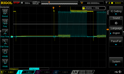
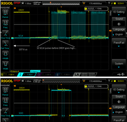
I essentially get no data output and DRDY does not go high when sending the SCLK pulses (which it should do after 8), except after the first conversion cycle where weird stuff happens. Here is the oscilloscope output:

Any help is greatly appreciated!

-- Dan

  • Hello Dan,

    First, welcome to the TI E2E Community!

    Getting 3-wire mode to work correctly can be challenging.

    When you read and write to the CONFIG4 and STATUS registers, are you using 24b frames for each of these?  If not, the ADC frames will be out of sync and conversion readings will be corrupted.

    In order to debug, I suggest not reading or writing to any registers after power-up and just try to read the conversion results.  The device will default to the internal clock and run at approximately 400ksps.  You will not be able to synchronize the 2 ADC's,  but this will help track down the problem.

    Please provide a zoomed in version of the first 2 frames; what SCLK frequency are you using?

    Regards,
    Keith Nicholas
    Precision ADC Applications

  • Hello Keith,

    Thanks for the quick response!

    Thanks to your input I was able to solve the problem. Your mention of the 24b frame size made me ponder about the possibility of my SPI communication being out of sync. I hadn't mentioned that I was toggling CS during the setup phase (reading and writing of registers). I didn't think this was a big deal because SPI communication worked just fine not matter how many times I sent a command. Apparently it messes up SPI communication for data retrieval after I toggle START high, somehow. Now I transmit a total of 10 bytes (1 write, 2 read commands) and add 2 bytes at the end to stay within the 24b frame before going into acquisition mode . I keep CS low at all times now (toggled low before resetting the device) and data output now works as it should!

    DRDY (yellow) & SCLK (cyan):

    Many thanks again!

    -- Dan