


Other Parts Discussed in Thread: ADS1248,
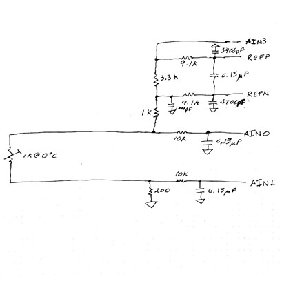
We are designing a board using the ADS122u04 to replace one designed with the ADS1248 and I'm stuck on configuring the IDAC. I don't seem to be able to get excitation current flowing. The circuit is a 2 wire configuration measuring the voltage on a platinum resistive sensor. The sketch shows the basic circuit23.
I'm able to communicate with the ADC122u04 to set and read the register settings. The settings are:
Desired Configuration:
// 00h - 0000 0000 - AINP = AIN0, AINN = AIN1, Gain = 1, PGA enabled (all of these are default settings)
// 01h - 0000 0010 - 20 SPS, Normal mode (256-kHz modulator clock), Single-shot conversion mode, External reference selected using the REFP and REFN inputs, Temperature sensor mode disabled
// 02h - 0000 0100 - No new conversion result available, Conversion counter disabled, Data integrity check disabled, Burn-out current source off, IDAC current 250uA
// 03h - 1000 0001 - IDAC1 connected to AIN3, IDAC2 disabled, Automatic data read mode
// 04h - 0100 1000 - GPIO2 output, GPIO1 input, GPIO0 input, GPIO2SEL DRDY, GPIO2DAT logic low, GPIO1DAT logic low, GPIO0DAT logic low
When I set the above configuration and then start a reading, the voltage on the circuit doesn't change (it doesn't seem to be getting any current). I do get a reading, but it varies around Vref (e.g. 8,300,261).
I think I'm doing something wrong in the configuration but I don't know what it is.
My code triggers a RESET, waits 10ms, writes to registers 01h-04h (I skip 00h because the defaults are what I want), reads all registers, and then sends a START/SYNC command, waits for a conversion, then repeats the START/SYNC.
Any help would be appreciated.
