This thread has been locked.

If you have a related question, please click the "Ask a related question" button in the top right corner. The newly created question will be automatically linked to this question.

ADC Signal chain adjustment

Other Parts Discussed in Thread: INA241A, OPA320, ADS8860, REF6050, ADS1220, TINA-TI, INA296A

Dear ladies and gentlemen,

I want to convert a PWM signal of 10sec. t_on and t_off (in total 20sec.), which is amplified to a range of approximately 1V to 4.5V.

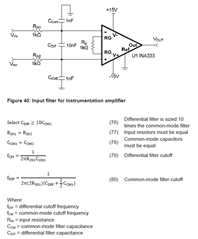
A buffer and RC filter will be added to the amplified signal. 

The resolution shall be 18 to 20 bit, so that the amplified signal will have high accuracy. Precision and therefore low noise shoud be focused on.

Therefore I need a adequate ADC.

I tend to use a DC optimized ΔΣ.

Are there any suggestions from your side to find an ADC and its matched comparator ?

Thank you for your help.

Regards

Oliver Makan

  • Hi Oliver,

    How often do you need to sample the PWM signal and is it a single channel application or will you need to convert multiple PWM signals? 

    This list of devices may be a good place to start, but I've reached out to some other team members to help with device selection. 

    https://www.ti.com/data-converters/adc-circuit/precision-adcs/products.html#p84=24;24&p1028=1;1&sort=p1130;asc

  • Hi Alexander,

    thank you for your reply. The sample rate is 1Hz because there is not the necessarity to sample so often.

    I chose the following signal chain:

    1. detection of signal via INA241A

    2. buffering via OPA320

    3. converting via ADS8860

    I might only have just 16 Bits resolution but hopefully a stable circuit.

    Can you recommend the selected components ?

    I have additional two questions following the selected components:

    1. With this signal chain, I wanted to implement another RC-Filter between the INA241A and the buffer (in addition to the charge bucket between buffer and ADC) because of the low frequency (the impact of noise might be even bigger then). Is it necessary to implement it and if yes, is there any method on how to dimension the RC-Filter without influencing the measured signal ?

    2. Is there any device for providing a stable reference voltage to the ADS8860 or can I just use the 5V supply voltage of the Opamps ?

    Regards

    Oliver

  • Hi Oliver,

    Just so I fully understand the design goals, you aim to create a buffered PWM signal (10s ON, 10s OFF) with a magnitude of 1V to 4.5V, then use an ADC to verify that the PWM signal is operating as intended? 

    What kind of application is this for? 

    These questions will help me connect you with the correct support personnel.  

    For what it's worth, the ADS8860 is a great device as it has a high sample rate and allows for up to a 5V input signal. If your application can spare extra clocks and memory, you could oversample the PWM signal to achieve higher resolution. However I'm not sure how much you will benefit from a device with this high of sample rate as the input signal and sample rate requirement is much slower. 

    The OPA and REF devices are supported by other product lines. Once we've decided on an ADC, I recommend opening additional E2E threads to connect with them.

  • To all,

    Just a brief comment to support the discussion.  Here is a link to a document describing filter+amplifier used with a PWM signal: Microcontroller PWM to 12bit Analog Out.  Based on the conversation, it seems that some of the information in the document may be useful.    Let me know if you have questions.  I support data converters now, but when I put this document together I was in the amplifier team.  Note that it will be chalanging to eliminate the ripple in the PWM signal to the point where it is a true 16 bit (i.e. the ripple is less than 1/2 LSB).

    Art

  • Oliver,

    A few other quesitons / comments:

    1. Regarding the ADS8860:  This is a good general purpose 16 bit SAR with sampling rates up to 1Msps.  The OPA320 is often paired with this device.  The REF6050 is a good choice for a voltage reference.  You can use the evaluation model schematic as a reference design if you want to use this set of components: ads8860evm users guide
    2. Of course, you can choose a DC optimized Delta-Sigma if you like (you originally mentioned that you prefer this kind of converter).  The ADS1220 is a good DC optimized 24 bit delta sigma with an integrated voltage reference.  This device will have a much lower sampling rate than ads8860, and will average the input signal while sampling.  So with the delta sigma option any ripple in the PWM signal will be averaged out, but for the SAR the voltage at the end of the acquisition period will be captured.  
    3. You can use TINA-TI or PSpice to simulate the entire signal chain (for the ADS8860 solution).  I can help you with this if you provide a schematic.

    best regards,  Art

  • Hi Alexander, hi Art,

    thank you again for your reply. That might be a good idea to introduce the application we try to build up. Maybe you will say that there is a completely other way to solve this. The purpose of the application is to detect the degree of aging of automotive fuses via measuring the voltage drop over them. For this we created an accelerated life test with pre-defined current pulses of 10 sec t_on and 10 sec t_off which accelerate the aging mechanisms within the fuse to get quicker results. The signal of interest is then the voltage drop over the fuse which need to get amplified because we expect (simulated) the value to be very low. Therefore the above mentioned INA241A will amplify the signal. After this we want to store the data in a MCU. Therefore we wanted to convert the signal via buffer and ADC. 

    : the Delta sigma sounds very interesting. Because of the expected very low voltage drop, the resolution/LSB must be very good. How does the implementation work. Do we need some different filtering or are you able to just replace it with an SAR. That would be a good idea to simulate it with your help.  After having a look at this comment I will send you a schematic. 

    Regards

    Oliver

  • Oliver,

    During the 10 sec t_on are you applying a PWM current to the fuse.  Or, are you applying a continuous current pulse for 10 seconds on then 10 seconds off.  I think you are applying a continuous current when on, but I want to confirm.  The reason I ask is I normally assume a PWM signal has a very fast frequency where the duty cycle is adjusted to change the average value.  If you are applying a continuous current pulse for 10 seconds, I really wouldn't call that "PWM".  The reason I am making that distinction is that devices like the INA241A is designed for fast transients in a traditional PWM signal.  For example, figure 8.1 illustrates a response to a 10us wide pulse.  I'm not saying that this INA would not work for your application, but I am saying that the PWM feature of this device may not be needed and this may make open the option to other current shunt monitors.  You should provide an image of the waveform you expect the INA to measure and post it on the current shunt forum.  Please post that figure here as well.

    Regarding the delta-sigma device (ADS1220):  It is a 24 bit converter and will have much lower noise.  Depending on the sampling rate and gain you choose, the noise can be in the single microvolt level (see table 1 in the data sheet).  Also, this device has an integrated voltage reference, and a high impedance input.  The SAR device (ADS8860) input will have transient current to charge the sample and hold.  For this reason a buffer is normally used with this device (OPA320 is a good choice).  This device is 16 bits and will have a higher noise (about 39uV rms).  The SAR can run at a much faster sampling rate (1Msps max), and will take a snap shot of the instantaneous voltage at the end of the acquisition period.  The delta sigma will give an average reading of what was measured during the sampling period.  Considering your have a long pulse period, I think you could make multiple measurement with the delta-sigma and average them.  You can drive the delta-sigma directly with your INA, and can even use its internal PGA to further amplify the output of the PGA.  Personally, I think the delta-sigma is probably the right choice for this application.  You can get evaluation modules for all of these devices and try experiments for proof of concept.  I suggest you do that.

    I hope this is helpful to you.

    Best regards,

    Art Kay

  • Hello Art,

    thank you for the proposal. You are correct when you say that its a DC current signal. I have the INA296A without PWM functions as an alternative device that might be interesting for this application. It has quite the same precision like the INA241A.

    Thank you for your hints. I will then try it with the ADS1220. Because of the very low frequency, there might be some noise. Is there a necessarity to imply filtering between the INA and the ADS ?

    What do you mean with evaluation modules ? 

    Best regards

    Oliver

  • Oliver,

    1. You do want some filtering between the INA and ADC.  This is for antialiasing.  Basically, you want this filter to have a cutoff frequency a decade or more below the modulator frequency.  For this device the modulator frequency options are listed in table 10 (256kHz to 512kHz depending on the mode).  So, you want the antialiasing filter below fmod/10.  You can see the typical configuration of a antialiasing filter in figure 74.  The filter is also shown below with its associated formulas.  If you set Cdif = 10nF, Ccm=1nF, and Rin = 1k ohm, you will get a cutoff of 7.57kHz.  You can adjust this according to your application, but these values are likely close to what you need.  This calculation and many others are located in the Analog Engineers Pocket Reference

    1. Most TI products have an evaluation module. This is a PCB with the device and associate required support circuitry.  For data converter evaluation modules, they normally include a microcontroller and software so that you can configure the ADC and collect data.  The ADS1220 has a nice evaluation module that you can plug into your USB port and collect data.  It also has locations for the input filter and easy input connections so you can connect your INA and filter and evaluate your entire signal chain.  See ADS1220EVM for the 1220 evaluation module. 

    I hope this is helpful to you.

    Art