This thread has been locked.

If you have a related question, please click the "Ask a related question" button in the top right corner. The newly created question will be automatically linked to this question.

AMC1304L05: Frequent device failures

Part Number: AMC1304L05

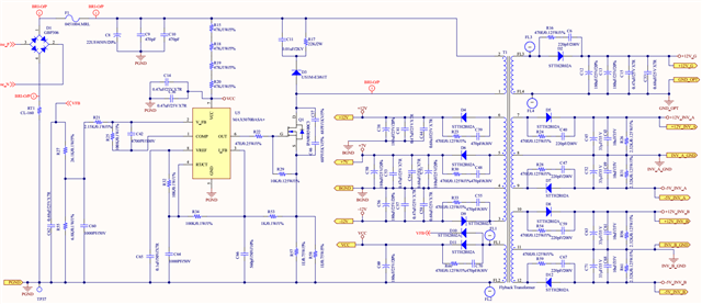
We're working on grid tie inverter & using AMC1304L05 for grid voltage & current measurement. We're seeing frequent failures of the device on grid voltage side. We're maintaining < 50mV at the AinP & AinN inputs @ 300Vac. Fig1. shows the schematics of voltage measurement. Fig 2. shows how we're tapping the AC input, also we're using AC side bias power supply using MAX5070.

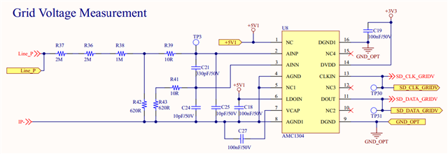
Fig 1. Grid voltage measurement
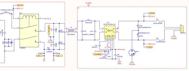
Fig 2. Grid Input


We're facing following issues:

1. The measured Grid Voltage spikes after sometime even when the grid input is stable (eg. it spikes to 280V & settle downs to 230V).

2. Randomly the device AMC1304 fails.

Need help in resolving the issue.

Thanks in advance.

  • Hi Pradeep,

    Can you please share the power supply schematic as well? 

    Can you describe in what way the AMC1304 fails? Is there noticeable damage to any pins? If so, which ones? 

    Looking at your schematic, there is most likely an issue with the amount of inductance (L3 & L4) between the positive input and the device ground. This inductance may cause leading/lagging spikes in the input voltage with respect to the device ground. This could be caused by the relay ADJ66012 switching in and out of the circuit as an inrush current is most likely created. 

  • Hi Alexander,

    Here is the Aux PSU schematic:

    There is no physical damage seen, the Device fails to respond when queried. The junk value is read instead of know value.

    Before the failure the value are read properly. Also, inductor L3 & L4 are not mounted and the relay is not populated.

    We're just validating the Vac & Iac reading before populating these components & going for grid tie.

    Thanks & Regards

    Pradeep

  • Hi Pradeep,

    I don't see the +5V1 or IP- net in this PSU schematic. 

    As shown in Figure 54. the input voltage should be measured across a sensing resistor where the negative input and ground are tied together to ensure that the common-mode input voltage specification is not violated. 

    This is not how your schematic is drawn, I don't see how the positive input voltage (Line_P) is referred to the negative or ground (IP-). More than likely this is leading to a common-mode input voltage violation. If you have access the high voltage probes, you can verify by measuring the voltage at the positive and negative input pins with respect to the high side ground.