This thread has been locked.

If you have a related question, please click the "Ask a related question" button in the top right corner. The newly created question will be automatically linked to this question.

ADS1119: Wrong ADC reading

Part Number: ADS1119
Other Parts Discussed in Thread: ADS1219

Hello,
I am having a problem as reading ADC value with ADS1119.

For I2C, the ACK response from ADS1119 is being received well. I can send CMD, write to config register 0x00 and also read back what I wrote.

However, the reading ADC value is constant all the time and quite different to what expected. (Expected :2.5V - Reading: 5V Full scale).

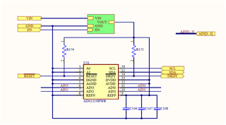
The ADC is configured as follow: input 2.5V AIN2-AGND, GAIN 1, 90SPS, Continuous conversion mode, External ref (5V).

I am not sure is there anything wrong here. Please let me know if there is any misunderstanding of the concept.

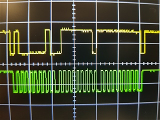
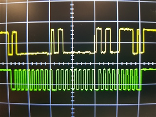
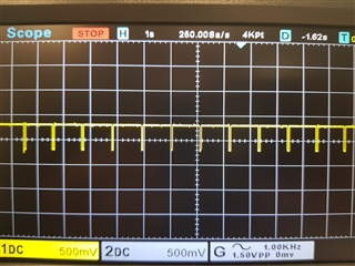
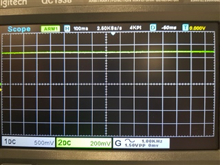
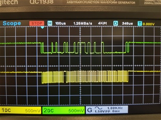
P/s: One more observation I made is when I try to read back 5 bytes, 3 first bytes contain value ( I expect only 2 following the ADS1119 datasheet).

I attached a screenshot of the communication when I try to read 5 bytes from the ADC.

Hope to hear from you soon. Thank you!

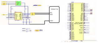
Here is the code I made to set up and read the ADC data:

// ADC set up
   // Reset device by common I2C 0x00 call
  Wire.beginTransmission(0x00);
  Wire.write(0x06);
  Serial.println(Wire.endTransmission());
  delay(500);
 
  // Read the value from the register 0x00 - should return 0 as default
  Wire.beginTransmission(0x40);
  Wire.write(0x20);
  Serial.println(Wire.endTransmission());
  Wire.requestFrom(0x40, 1);
  if (Wire.available() == 1) {
    int value = Wire.read();
    Serial.println(value);
  }
  delay(100);

  // Write a value to the register 0x00 - 0xA7 - 1010 0111 : AIN2AGND, GAIN 1, 90SPS, Continuous conversion mode, External ref 
  Wire.beginTransmission(0x40);
  Wire.write(0x40);
  Wire.write(0xA7);
  Serial.println(Wire.endTransmission());
  delay(100);

  // Read the value from the register 0x00 - should return 0xA37= 0d167
  Wire.beginTransmission(0x40);
  Wire.write(0x20);
  Serial.println(Wire.endTransmission());
  Wire.requestFrom(0x40, 1);
  if (Wire.available() == 1) {
    int value = Wire.read();
    Serial.println(value);
  }
  delay(100);

  // Start conversion
  Wire.beginTransmission(0x40);
  Wire.write(0x08);
  Serial.println(Wire.endTransmission());
  delay(1000);

// main loop

  //Reading data by cmd
  uint16_t value;

  Wire.beginTransmission(0x40);
  Wire.write(0x10);
  Wire.endTransmission();
  Serial.print("Number of bytes requested :"); Serial.println(Wire.requestFrom(0x40, 2));
  Serial.println();
  value = (Wire.read() << 8 | Wire.read());
  if (value > 0x7FFF)
  {
     value = 0x0;
  }
  float voltage = 5.0 * (float(value) / 32767) * 1;
  Serial.println(voltage);
  delay(1000);
  • // ADC set up
       // Reset device by common I2C 0x00 call
      Wire.beginTransmission(0x00);
      Wire.write(0x06);
      Serial.println(Wire.endTransmission());
      delay(500);
     
      // Read the value from the register 0x00 - should return 0 as default
      Wire.beginTransmission(0x40);
      Wire.write(0x20);
      Serial.println(Wire.endTransmission());
      Wire.requestFrom(0x40, 1);
      if (Wire.available() == 1) {
        int value = Wire.read();
        Serial.println(value);
      }
      delay(100);

      // Write a value to the register 0x00 - 0xA7 - 1010 0111 : AIN2AGND, GAIN 1, 90SPS, Continuous conversion mode, External ref 
      Wire.beginTransmission(0x40);
      Wire.write(0x40);
      Wire.write(0xA7);
      Serial.println(Wire.endTransmission());
      delay(100);

      // Read the value from the register 0x00 - should return 0xA37= 0d167
      Wire.beginTransmission(0x40);
      Wire.write(0x20);
      Serial.println(Wire.endTransmission());
      Wire.requestFrom(0x40, 1);
      if (Wire.available() == 1) {
        int value = Wire.read();
        Serial.println(value);
      }
      delay(100);

      // Start conversion
      Wire.beginTransmission(0x40);
      Wire.write(0x08);
      Serial.println(Wire.endTransmission());
      delay(1000);

    // main loop

      //Reading data by cmd
      uint16_t value;

      Wire.beginTransmission(0x40);
      Wire.write(0x10);
      Wire.endTransmission();
      Serial.print("Number of bytes requested :"); Serial.println(Wire.requestFrom(0x40, 2));
      Serial.println();
      value = (Wire.read() << 8 | Wire.read());
      if (value > 0x7FFF)
      {
         value = 0x0;
      }
      float voltage = 5.0 * (float(value) / 32767) * 1;
      Serial.println(voltage);
      delay(1000);
  • Hi Thanh Dat Le,

    Welcome to the E2E forum!  I don't see anything specific to your code that may be an issue.  You say you are applying 2.5V to the input, but what code is being returned by the ADS1119?  It would be better to see the actual code values so can you capture each byte being transmitted prior to calculation?  This helps eliminate a computational error.

    It is not clear why you are trying to read more data than the size of the ADC conversion result.  If you suspect that you are getting more data returned make sure that you are using the ADS1119 (16-bit) and not the ADS1219 (24-bit).

    The scope shot is helpful, but it is difficult to determine the result.  It would appear to be 0x6F61.  This would appear to be too high for a 2.5V input.  Make sure that your supply voltage is 5V and not 3.3V.  If it is 3.3V the returned value is much closer to 2.5V.

    Also make sure that your input source is at the same ground potential as the ADS1119.

    Best regards,

    Bob B

  • Hi Bob,

    thank you so much for fast response. 

    For 2.5V input, the ADC returned 0x7FFF all the time. I tried to config ADC into single shot mode and send START cmd every 1s, same results returned.

    Here is screenshot of the communication when I read 2 bytes from the ADC, seems like it matched which I got (0x7FFF). 

    I verified the supply voltage 5V, ref voltage 5V and the input 2.5V . All goods and they share the same ground potential. 

  • I'm not well versed with Arduino, but I believe wire.endtransmission(); defaults to sending a stop bit.  After your RDATA (write 0x10), try using wire.endtransmission(false); to send a repeated start as the datasheet requires.

    Ben

  • Hi Thanh Dat Le,

    As Ben has stated, using repeated start is preferred as it prevents another device from grabbing the I2C bus between the write and read.  However, it is not required and does not appear to me to be the issue.  As you are getting data, it is more likely that you are reading conversion data that is using the internal reference instead of the external.  Can you show scope shots for both of the register write and also the register read for the configuration register?  Another verification that the register was written is by checking the DRDY pin to see if it is toggling at the desired data output rate.  You should see this pin toggling following the issue of the START command.

    I didn't notice this before but you are declaring the variable name 'value' twice.  Once as an 'int' and later as a 'uint16_t'.  Also 'uint16_t' is not a standard Arduino data type.  For the conversion data you can directly store the result into a 'short' data type.  As the conversion data returned is binary 2's complement, the correct value will be stored into the 'short' as a signed value.  For the register data you can can set the variable to a 'byte' type which is 8 bits unsigned.

    Best regards,

    Bob B

  • Hi Bob, 

    thank you for your advice on variable name and data type!

    Here are the screen shots of communication when I was writing and reading 0xA7 to/from config register: 

    Writing 

    Reading

    Here is the DRDY pin when I was sending START cmd and followed by READ cmd every 1s:

    Everything seems to be alright. I am not sure is there anything wrong here.

  • Hi Ben, 

    I tried to send a repeated start by using wire.endtransmission(false), seems like it doesnt solve the problem.

    Thank you for your support !

  • Hi Thanh Dat Le,

    I'm confused by your scope plot for DRDY.  What I see appears to be only one conversion a second.  Maybe you need to zoom in as I cannot tell if the ADC is toggling the DRDY pin during what looks like the low period in the scope plot.  What you should see is DRDY toggling the whole time if the ADC is in continuous conversion mode.

    What may be happening is a power issue or perhaps some form of an ESD or transient event that is resetting the ADS1119.  It doesn't appear that you have any analog input protection or input filters.  A transient event can reset the ADS1119 which will also reset the configuration back to default.

    Another possibility is something in your code is not functioning as you expect.  Can you attach your sketch as a file for me to review?

    Best regards,

    Bob B

  • Hi Bob,

    here is the screen shot for DRDY when ADC was put on continuous conversion mode (90SPS).


    We expected the DRDY toggle every 1000/90 = 11ms but it seems like the signal is high (no conversion) all the time. 

    Do you have any conclusion on this ADS's behaviour?

    P/s: I also checked the content of config register every 1s and pretty sure that the ADC was not resetted to default value. 

  • These devices are dead simple - after a start command, in continuous conversion mode, there's not much that would prevent them from at least toggling DRDY.  As long as RESET isn't being pulled low for some reason, I'm inclined to think the device is damaged.

    What happens if you set the MUX to 0b111?  You should get ADC values near zero.

  • Hi Thanh Dat Le,

    I will guess that you are using some form of prototyping system.  Can you send pictures of your setup?  Also, I ask again for the code attached as a file so that I can attempt to replicate.

    Best regards,

    Bob B

  • Hi Bob, 

    here is the test code and my testing setup: an external Arduino Uno was used to read data from the on board ADC. Analog input signal (2.5V) was generated by a STM32. There is only one ADS1119 connecting to I2C line (pulled up to Vcc with 1K resistor). The reason why we used Arduino to test is we also receive same wrong value (0x7FFF) when reading ADC value using STM32 before.


    ADS1119.txt
    #include <Wire.h>
    
    void setup() {
      Wire.setClock(100000);
      Wire.begin();
      Serial.begin(115200);
    
      // checking the I2c device on the line
      byte error, address;
      int nDevices;
    
      Serial.println("Scanning...");
    
      nDevices = 0;
      for(address = 1; address < 127; address++ )
      {
        // The i2c_scanner uses the return value of
        // the Write.endTransmisstion to see if
        // a device did acknowledge to the address.
        Wire.beginTransmission(address);
        error = Wire.endTransmission();
    
        if (error == 0)
        {
          Serial.print("I2C device found at address 0x");
          if (address<16)
            Serial.print("0");
          Serial.print(address,HEX);
          Serial.println("  !");
    
          nDevices++;
        }
        else if (error==4)
        {
          Serial.print("Unknow error at address 0x");
          if (address<16)
            Serial.print("0");
          Serial.println(address,HEX);
        }    
      }
      if (nDevices == 0)
        Serial.println("No I2C devices found\n");
      else
        Serial.println("done\n");
    
    
     // setting up 
       // Reset device by common 0x00 call
      Wire.beginTransmission(0x40);
      Wire.write(0x06);
      Serial.println(Wire.endTransmission());
      delay(500);
      
      // Read the value from the register 0x00 - should return 0 as default
      Wire.beginTransmission(0x40);
      Wire.write(0x20);
      Serial.println(Wire.endTransmission());
      Wire.requestFrom(0x40, 1);
      if (Wire.available() == 1) {
        int value = Wire.read();
        Serial.println(value);
      }
      delay(100);
    
      // Write a value to the register 0x00 - 0xA7 - 1010 0111 : AIN2AGND, GAIN 0, 20SPS, Cont mode, External ref
      Wire.beginTransmission(0x40);
      Wire.write(0x40);
      Wire.write(0xA7);
      Serial.println(Wire.endTransmission());
      delay(100);
    
      // Read the value from the register 0x00 - should return 0xA7 = 0d167
      Wire.beginTransmission(0x40);
      Wire.write(0x20);
      Serial.println(Wire.endTransmission());
      Wire.requestFrom(0x40, 1);
      if (Wire.available() == 1) {
        int value = Wire.read();
        Serial.println(value);
      }
      delay(100);
    
      // Start conversion
      Wire.beginTransmission(0x40);
      Wire.write(0x08);
      Serial.println(Wire.endTransmission());
      delay(1000);
    
    }
    
    void loop() {
    
    // // Start conversion
    //   Wire.beginTransmission(0x40);
    //   Wire.write(0x08);
    //   // Wire.write(0x41);
    //   Serial.println(Wire.endTransmission());
    //   delay(100);
    
    //Read data by cmd
      uint16_t value;
      // Reading data by cmd
      Wire.beginTransmission(0x40);
      Wire.write(0x10);
      Wire.endTransmission(false);
      Serial.print("Number of bytes requested :"); Serial.println(Wire.requestFrom(0x40, 2));
      Serial.println();
      byte value_1 = Wire.read();
      byte value_2 = Wire.read();
    
      Serial.print("Byte 0:"); Serial.println(value_1);
      Serial.print("Byte 1:"); Serial.println(value_2);
    
      value = (value_1 << 8 | value_2);
      if (value > 0x7FFF) 
      {
        value = 0x0;
      }
      //Serial.println(value);
      float voltage = 5.0 * (float(value) / 32767) * 1; 
      Serial.print("Vin :"); Serial.println(voltage);
      Serial.println();
    
      delay(1000);
    }

  • I think what Bob is asking for is a picture of your actual physical setup.  A camera-phone picture, for instance, of the bench with your devices and connections visible.

    It would still be helpful to see what result you get with MUX=0b111

  • Hi Thanh Dat Le,

    I will review and get back to you tomorrow.

    Best regards,

    Bob B

  • Hi Ben, 

    For MUX=0b111, the returned result is constant 0xFFFF (~0), however, the DRDY was not toggling at all so I am not sure that is the true value or not.

  • Hi Bob, 

    I also sent a picture of actual setup to you through direct message, pls check it. Thank you! 

  • Hi Ben, Bob

    it seems like we were provided by a block of clone chips. Thank you so much for helping me these days. 

  • Well I guess my inclination to think the device was damaged wasn't too far off.

    Glad you got it sorted.