This thread has been locked.

If you have a related question, please click the "Ask a related question" button in the top right corner. The newly created question will be automatically linked to this question.

ADS7057EVM-PDK: No output from the EVM board

Part Number: ADS7057EVM-PDK
Other Parts Discussed in Thread: ADS7057, , ADS7056, ADS7052

Hi,

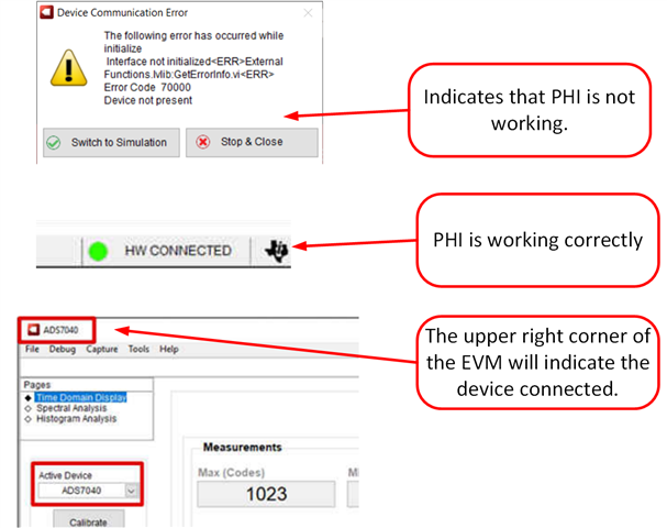
   We are using a ADS7057EVM-PDK to evaluate ADS7057 ADC. The EVM is connected to a PC through a PHI module. The data is acquired using ADS704X-5XEVM-PDK-GUI installed in a PC.

The details of the devices we are using are as follows.

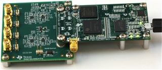
  • Evaluation Module Name: ADS7057EVM-PDK      - DC019A
  • PHI controller: PA007

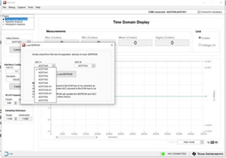
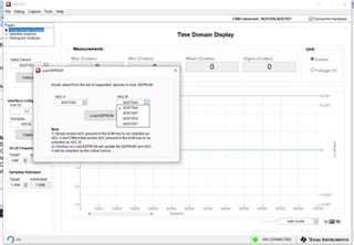
During the initial setup there was a message which says no valid device EEPROM configuration found. So we used the EEPROM configuration utility to set the ADC1 as ADS7056 and ADC2 as ADS7057.(Note that as per the user guide of  ADS7057EVM-PDK - DC019A both devices are ADS7057 but in the configuration utility the devices available were only ADS7056 for ADC1 and ADS7057 is available in ADC2)

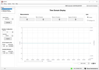
But the captured output code is always shown as '0' in both ADCs, not even a noise voltage is coming at its output. We applied input  sine and DC waveforms also to check. But the output is always '0'

Please provide a solution

Regards

    Varun M J

  • Varun,

    1. Sorry for the difficulty you are having. The EEPROM should have been properly programed out of the box.  Below are some steps to troubleshoot this issue further.
    2. Did you de-solder or re-solder any devices on the EVM? Based on your comments you want to evaluate the ADS7057.   This device is already installed in the U5 position.  Nevertheless, you mentioned that both devices are ADS7057.  Can you clarify the situation?
    3. Note: when writing to the EEPROM the EEPROM jumper must be set in the WR_EN position.
    4. Please try the following:
      1. Completely unplug the EVM.
      2. Make sure that the PHI is securely mated to the ADS7057EVM.
      3. Plug the EVM back into your PC.
      4. Restart the software.
      5. Did the software start properly? If it did not start properly a pop-up will say “Device communications Error” (see below).  If it did start properly, you should see a green “HW connected” indication at the bottom of the GUI (see below).
      6. The upper right corner should indicate the device connected (see below).
    5. If step 1 above shows no errors then the issue is not the EEPROM. In this case, the reason you are measuring a zero code is not related to the EEPROM programing.  If this is the case we should look at the power and input signals.  Let me know these levels.
      1. Signals applied to the inputs of the device (U5). What are they?
      2. Check OPA_VDD, AVDD, DVDD and AVDD/4 supply levels.
    6. Hopefully some of the tests above provide some insight into the issue. If not I will have additional trouble shooting recommendations. 

    Art

  • Hi,

    Thank you for the reply.

    We are using the ADS7057 Evaluation Module - PCB No. DC019A. (User Guide SBAU302 – December 2017). You are referring to the EVM with PCB No DC123 based on the user guide SBAU382A – NOVEMBER 2021 – REVISED JANUARY 2022.

    The DC019A has two ADS7057 ADC with option for differential inputs.


    Answering your questions

    1. When we initially connected the device and then ran the GUI there was a message pop up which read that the EEPROM configuration is wrong. So we used the Load EEPROM utility to load the EEPROM. But in the Load EEPROM we found that only for the ADCA the options available were ADS7052, ADS7056 etc. There was no ADS7057. But for ADCB there was the option for ADC7057. So we loaded the configuration with ADCA = ADS7056 and ADCB = ADS7057.


    2. We didnt de-solder / solder any devices. As mentioned above the EVM we purchased has the PCB no. DC019A which supports 2 nos of ADS7057. But the load EEPROM utility only allowed us to set ADCA as ADS7056 and ADCB as ADS7057.

    3. We set the EEPROM by connecting EEPROM write enable jumper as per the user guide SBAU302

    4. The device seems to be properly connected and "HW Connected" indication in the GUI is green

    5. We measure the supply voltages as below

    V_OPA = 5V; AVDD = 3.3 V; DVDD = 3.3 V; Vref/2 = 1.65V

    Also we tried to capture the SPI signals SCLK, SDO and CS of the ADCs and we observed the following

              In the GUI, when we are selecting the active device as ADS7056(ADC A).

    • Clock is present in both ADC A and ADC B (signal SCKL_AB)
    • CS signal transitions are absent in ADC A (signal CS_A) but present in ADC B (signal CS_B)
    • There is data in the SDO of ADC B (SDO_B)

             In the GUI, when we are selecting the active device as ADS7057(ADC B).

    • Clock is present in both ADC A and ADC B (signal SCKL_AB)
    • There are no transitions in the CS signal of both ADC A (signal CS_A) and ADC B (signal CS_B)

    I am also attaching the User guide for the board we are using

    ads7057evm-pdk.pdf

  • Varun,

    Thanks for your very clear explanation.  The problem is that the EVM that you purchased has been updated and the software, and users guide have been updated to correspond to the new hardware.   I can send you an new EVM at not cost.  If you are interested in this, please send me your contact information via E2E private message.  I think you will have to do a friend request to send the message.  Alternatively, we can look into the process of getting the old software for you.  This may take some time and effort as we will have to setup a secure software link and get internal approval.  Sorry for the difficulty you are having with this.

    Best regards,

    Art

  • Thank you Art Kay for your help with the issue...

    I will send you the friend request and then share my contact details.