This thread has been locked.

If you have a related question, please click the "Ask a related question" button in the top right corner. The newly created question will be automatically linked to this question.

ADS1119: Schematic diagram help

Part Number: ADS1119

Hi,
I need to connect 6 pressure sensor input and 1 LVDT sensor. I am actually looking for the schematic diagram, I have prepared one. Please find in attachment. 
also please help me with A0,A1 address line selection. Like how to select particular AINx(x=0,1,2,3) from the two ADC chip is being controlled by the same I2C channel.
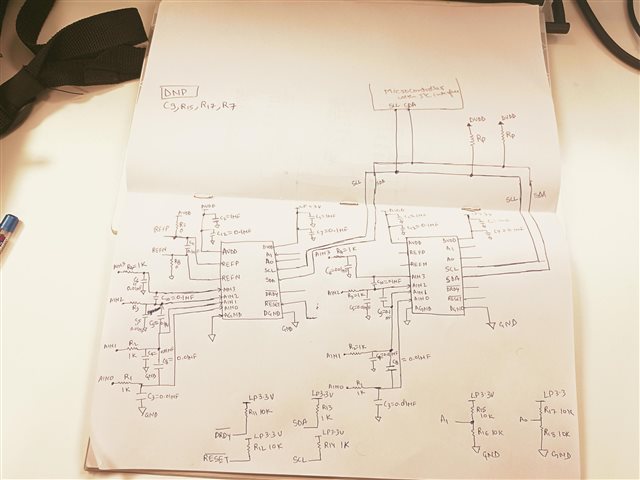
Thanks and Regards,
Abhishek Duivedi 

  • Hi Abhishek,

    If you are planning on using an external reference, you need to supply it externally.  If you want to supply the reference from AVDD, then you will need to install R7.

    If you are connecting your pressure sensors as single-ended (referenced to GND), then you will not need to install the differential input capacitors.  If you do connect differential input capacitors (like for the differential input device) then the differential cap needs to be at least ten times greater in value compared to the common-mode capacitors.

    The address pins to the ADS1119 cannot be connected to the same address. This means you cannot use the scheme you show in the drawing.  You could connect one device to have A0 and A1 connected to GND (address 0x40) and the 2nd device have A0 and A1 connect to the DVDD supply (address 0x45).  This will allow 2 separate address for the devices when communicating with the microcontroller.

    Both ADCs are connected to the same DRDY connection.  This can work, but it will be difficult to know which device triggered the DRDY.  The Status register can be read to verify if the conversion is new and ready to read out from the device.

    Best regards,

    Bob B