This thread has been locked.

If you have a related question, please click the "Ask a related question" button in the top right corner. The newly created question will be automatically linked to this question.

ADS7066: Delay time

Part Number: ADS7066
Other Parts Discussed in Thread: ADS8900B

Hi Team,

Can you please help us with this inquiry of our customer.

From the datasheet, the D_CKCS: SCLK launch edge to (next) data is valid on SDO. What is the launch edge, leading or trailing edge? The CPHA and CPOL are 0.

We run ADS7066 SPI at 50MHz and want to understand the SDO timing to confirm that it is "clocked out" by the SCLK trailing edge.

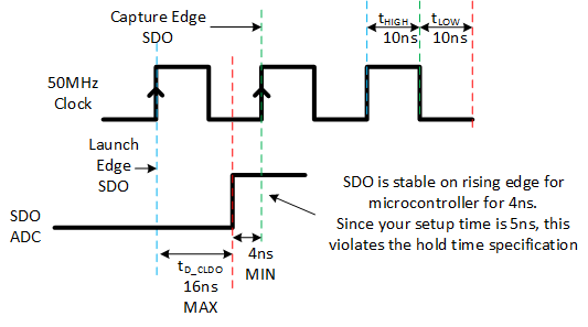
The tD_CKDO MAX = 16 nS is making problems in our design.

What is the tD_CKDO MIN? The MAX exceeds the half SCLK cycle that makes it misses the following SCLK leading edge. The SPI Master device has the Master (MOSI) input setup = 5 nS min

Typically, the data output (SDO) valid max + data input (SDI) setup min <= SCLK cycle / 2

Regard,

Danilo

  • Danilo,

    I understand the confusion, as in normal SPI-00, data will be captured on the rising edge and transition on the falling edge of SCLK.   I believe that this device is using what we call “early data launch”.   For this example, consider SPI-00, where the data is capture on the rising edge of the clock.   In this case the first SDO data bit will transition on the falling edge of chip select.  This data is captured by the microcontroller on the first rising edge of the clock.  The second SDO data bit will transition on the first rising edge of the clock.  All subsequent SDO bits transition on the SCLK rising edges and are also captured on the rising edge by the microcontroller.  The hold time of the ADC will keep the SDO signal stable so that on each rising edge the data will be valid before the transition of SDO occurs.  The ADS8900B gives a good explanation of this in section 7.5.4.2.1 Legacy, SPI-Compatible (SYS-xy-S) Protocols.  I believe this is how it operates but need to confirm.

    I have an EVM on order, to confirm this.  Can you slow the clock down and confirm that SDO will transition on the rising edge of the clock as well as when CS drops low?

    Best regards,  Art

  • Danilo,

    I confirmed that the device operates as described above.  You can look at figure 60 in the ADS8900B data sheet to see how the data is launched and captured.  In short, for SPI-00 data is launched and captured on the rising edge.  The MSB is launched on the falling edge of CS.  Let me know if you have further questions.

    Art

  • Hi Art, so the ADS7066 in SPI-00 mode the SCLK launch edge is the leading (rising) edge that clocks out SDO. Under the following conditions:

    ADS7066 tD_CKDO MAX = 16 nS

    Our SPI Master input setup min = 5 nS

    SCLK = 50 MHz or 20 ns clock cycle

    The SPI Master won't be able to latch the SDO on the following rising edge. The 16 nS is the max, if it the actual tD_CKDO <= 15 nS, then the Master is possible to latch the SDO on the following rising edge, As you can see, this timing situation can go either way randomly.

    What do you suggest to make a reliable 50 MHz operation?

    - Vance

  • Vance,

    You are correct.  At the maximum 16ns delay time, the signal will only be valid for 4ns and this will not meet your microcontroller setup time (see figure below).  In this case your options are to reduce the clock rate or choose a different device that has a shorter delay.  I don't know of any other approach.

    Best regards,

    Art

  • Hi Art, thanks, it confirmed my understanding. So how does ADS7066 support daisy-chain mode at higher SCLK? There are tD_CKDO 16 nS and tSU_CKDI 6.4 nS. It limits the clock to at around 44 MHz, but the data sheet says SCLK max is 60 MHz.

    To reach the 60 MHz that ADS7066 claims, it requires a Master with 0.6 nS input setup time that probably doesn't exist. We chose this device because of the package  size and the SCLK exceeds our 50 MHz requirement...

  • Vance,

    1. You are correct on the daisy-chain.  The same figure in my post above applies.  The at worst case the SDO signal will have a delay of 16ns MAX.  Since SDO is the signal applied to SDI the SDI signal will be stable for 4ns before the clock rising edge.  The setup required for SDI is 6.4ns, so this isn't sufficient setup.  The device does not have the same max clock for daisy chain as it does for normal operation.
    2. I also agree with you that 60MHz may be difficult to achieve with many microcontrollers.    The 0.6ns setup time allotment is very short.  
    3. You have some good points regarding these specifications.  I will feed this back to the product definition team.
    4. I hope you can find an alternative, or can reduce the clock speed.

    Best regards,  Art

  • Hi Art, thanks for your expertise on this issue and timely responses. We will follow your advice then move on.  - Vance