This thread has been locked.

If you have a related question, please click the "Ask a related question" button in the top right corner. The newly created question will be automatically linked to this question.

ADS1261: Delta-Sigma ADC Evaluation software

Part Number: ADS1261

Hi Team, 

Good day. I am posting this inquiry on behalf of the customer.

I have a question regarding the "Delta-Sigma ADC EvaluaTion software - ADS1261"
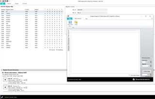
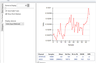
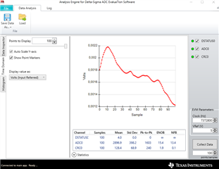
I am trying to measure the GPIO Pins with the Data Analysis Tool
but I don't see any channels being enabled
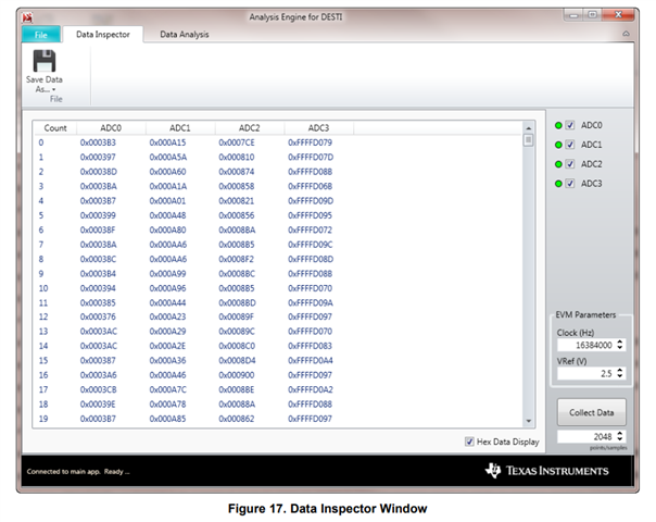
normally there should be the channels I enabled on the right side
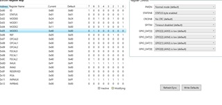
but for me, there are no checkboxes
I enabled the GPIO pins and also the STATENB
in the STATUS register, I can't change the LOCK section ... why is that so?
Please help to advise. Thank you for extending your support.
Kind regards, 
Marvin
  • Hi Marvin Cantos,

    One important point about the EVM GUI is that the Data Analysis tool defaults to 2048 samples. Also, the ADS1261 defaults to a data rate of 20 SPS (both default settings are selected in the images provided above). This means that it will take ~100 seconds for data to be available, and unfortunately there is no real indicator in this GUI to let you know that data is being processed. Please have the customer reduce the number of samples or increase the data rate to something more reasonable

    I also noticed in the images above that the user has selected INPMUX = 0xFF. This sets both ADC measurement channels (MUXP and MUXN) to VCOM, which is the equivalent of shorting them to mid supply. This is the correct process to measure the ADC noise, but it will not help the user measure the GPIO pins if that is their intent. They need to enable the correct measurement channels in the GUI.

    -Bryan

  • Hi Bryan, 

    Thank you for your response. Please see the feedback from our customer.

    "The Problem is basicly: I want to use the data analysis tool by just activating a GPIO pin and measuring some noise since nothing is connected yet. Just to check if I can get any voltage values/codes."

    Please help to advise. Thank you for extending your support.
    Kind regards, 
    Marvin
  • Hi Marvin Cantos,

    Did the customer try any of the things I suggested? If so, what happened?

    -Bryan

  • Hi Bryan, 

    Thank you for the prompt response. Please see the feedback from our customer.

    "I did not see the feedback Link the First time.
    I will try it again tomorrow."

    I will update once the customer provides feedback.
    Thank you for extending your support.
    Kind regards, 
    Marvin
  • Hi Bryan,

    i tried the following (everything else is still the same (see pictures)):

    - i changed the SPS rate and lowered the collection data number

    - changed the INPMUX channels to "No connection"

    When starting the Data Analysis tool i still dont see any channels ("Available channels to display and view") on the right side of the tool.

    What exactly do i still need to do ? You said: ... need to enable the right measurments channels in the GUI ...". 

    Thanks in advance for the reply and best regards,

    Marcel

  • Hi Marcel Beck,

    I did not see any new pictures in your latest response. What happens when you hit "Collect Data" in the Data Analysis tool?

    Perhaps the ADS1261EVM device package did not install properly. The installation requires two downloads and installs. The first is the main application (Delta-Sigma ADC EvaluaTIon Software) and must be installed first. The second is the device package (ADS1261EVM-DVCPKG) found on the ADS1261EVM web page. I would try reinstalling the device package.

    You can verify if the device package installed correctly by searching in the 'Documents' folder. You should see a subfolder in: Documents\DSEvalSW\Devices\ADS1261

    Also, sometimes when you start the GUI and then plug in the EVM, the EVM is not recognized so try plugging in the EVM and then start the GUI

    Let me know if any of these suggestions help

    -Bryan

  • there was no problem with both installations. I also see the device folder ADS1261.

    I did not unplug or plug in the EVAlBoard when the software was already running.

    I was refering to the first pictures i send since i only changed the two points above.

    In the first picture (data analysis tool GUI) there should be checkboxes of the enabled channels .... but there are none for me, even so i enabled the GPIOs and set them to input.

    Best regards,

    Marcel

  • Hi Marcel Beck,

    When I powered up my ADS1261EVM, launched the GUI, changed no registers, and enabled the Data Analysis tool, the first image below shows what I saw. I don't see the checkbox you are referring to on the right hand side.

    Then, I changed the "points/samples" to 20, hit "Collect Data, and the second image shows what I received. Here, I do see the checkbox, though this only tells you that "ADC0" was measured. In other words, it will not tell you which channels are measured, so you need to confirm this by reading the register map (INPMUX register)

    The data I am showing is using the default ADC settings, where both ADC inputs are shorted to VCOM. That is why you see small decimal values because this is just the ADC noise at the chosen settings.

    Can you follow this procedure and let me know what happens when you do? If the outcome is different, please let me know how it is different and what happens.

    -Bryan

  • Thanks for the detailed response and the pictures. I just tried it and can confirm that it also works for me :)

    I will now try to measure all of the other channels.

    if i encounter any further problems i will get back to you after the weekend.

    Thanks again and best regards,

    Marcel

  • Hi Marcel Beck,

    I am glad we could help

    -Bryan

  • i am making some progress understanding the EvalBoard. Setting the the IMPMUX of two channels lets more measure (with the data analysis tool) the voltage between those two channels.

    How can i get the measurement of more channels simultaneously like it is shown in the sbau260 manuel (see picture below). 

    Here four ADC-channels are measured while i can only measure one (ADC0 which equals in my case the GPIO2&3).

    I want to measure all of the GPIO-Pins at the same time, respectively the voltage difference between those.

    Best regards,

    Marcel

  • Hi Marcel Beck,

    Since the ADS1261 is a multiplexed device with only 1x ADC, you can only measure 1x channel at a time using the GUI. The image you are showing would be for a simultaneous sampling ADC that has multiple ADCs in one package.

    Also, irrespective of the GUI, the ADS1261 can still only measure only channel at a time. Therefore, even if you wrote your own code and fly-wired your own controller into the EVM, you would still only be able to measure one GPIO at a time. That is, you would set the mux to GPIO0, then take a measurement, then send the command to switch the mux to GPIO1, then take a measurement, then switch the mux... and so on.

    I hope the operation of this ADC is more clear now

    -Bryan

  • Thanks for the good explanation. 

    I'll set up a measurement setup and write a script right away.


    Many thanks and best regards


    Marcel

  • Hi Marcel Beck,

    Ok, let us know if you have additional questions

    -Bryan

  • Dear Bryan,

    i am setting up my measurement and picking a constant current source but unfortunately when i measure my GPIO pin (current source) i only measure a lower value from what i have initiated. (17,8 µA measurement and 100µA set)

    The picture below shows what i have initiated: 

    I am measuring (multimeter) µA from Ground to the respectively pins (AIN2, AIN3)

    Additionally: what exactly is happening when i set the MODE3: GPIO_DAT from low to high? (why is the current output changing by alot?

    Thanks in advance and best regards,

    Marcel

  • Hi Marcel Beck,

    Can you show how your circuit is connected? What are AIN2 and AIN3 connected to?

    I am not really sure what you are trying to go with the GPIO pins. GPIOs are intended to send or receive logic-level signals e.g. 0 or 1. Setting GPIO_DAT = high sets the voltage on the selected GPIO pin to AVDD, which is likely 5V in your case. Setting GPIO_DAT = low sets the voltage on the selected GPIO pin to 0V.

    I would strongly encourage you to review the pertinent sections in the datasheet for more information. Many of your questions could have been answered by reading that document. If you are going to use the IDACs, please read that section (9.3.6). If you are going to use the GPIO, please read that section (9.3.7)

    -Bryan

  • AIN2 and AIN3 are not connected to anything. 

    I just set these two GPIOs as outputs and have excited 100µA. Afterwards  measured with a multimeter the current which goes from each pin to the ground.

    I expected to be 100µA but it was only 17.8µA and 18,0µA for the other pin. I repeated the measurement with another board and a different multimeter, the results were 30µA and 22µA.

  • Hi Marcel Beck,

    I think we need to distinguish between GPIOs and IDACs. General purpose input / output (GPIO) pins define a logic level relative to AVDD for the ADS1261. Current DACs (IDACs) output a known current to bias sensors. I am not sure why you would want to use both of these features at the same time on the same pins.

    If you are changing the IMUX and IMAG registers in the GUI, this is turning on the IDACs, not the GPIOs. According to the screenshot you sent, you enabled the IDACs on AIN2 and AIN3. You also set the GPIOs to be connected to AIN2 and AIN3, then specified them as outputs. What are you trying to accomplish here?

    With nothing connected to AIN2 and AIN3, where is the IDAC current going to go? Are you trying to short it to ground through the GPIO? I am very confused at what the goal of these experiments is.

    If you want to get current out of the pins, please place something like a 1k resistor between AIN2 and ground, then measure the voltage across this resistor to confirm that the current is ~100uA

    -Bryan

  • Dear Bryan,

    first of all thanks for all the effort you put into answering my questions.

    I now understand where my thought process was wrong. 

    I thought to set my pin as a current source i need to set IMUX and IMAG << after i enabled the pin with MODE2 and setting is as an output for the current to "get out" >>

    All of the "<<...>>" like you mentioned was wrong/not necessary to do, but by doing so i messed up the current output !

    I now only set IMUX, IMAG and enabled REFNB (int enabled) and now i measure the right current value.

    Thanks alot Slight smile

    best regards,

    Marcel

  • Hi Marcel Beck,

    You are welcome!

    -Bryan

  • Hi Bryan,

    i have some questions regarding the MODE1: 4-wire AC excitation mode. From what i understood is that this mode enables the EXC_out+ & EXC_out- and switching polarity like it is shown in the figure below.

    What is the timing of the of SW=On and is the t_d(ACX) equal to the MODE1: DELAY (in my case 50µs (default)) ?

    How can i change the timing/frequency of the measurement time ?

    I am currently using the predefined script External bridge - external reference w/ AC excitation. I am not quite sure why AIN3/4 are configurated as outputs and afterwards AIN2/3 are configurated as inputs. Also why does it set the GPIO[2] pin as HIGH?

    Best regards,

    Marcel

  • I think i can answer the first question by my own:

    The frequency is ~400Hz from +-5V.

    Still i have no idea how to change it or if it is even possible to do so

  • Hi Marcel Beck,

    The AC excitation mode timing is given in the datasheet - I copied this info below. STDR refers to Table 8

    The AC excitation mode uses the GPIO pins to control external switches. On the EVM, this external "switch" is a gate driver. So the device is toggling the GPIOs in order to switch the polarity of the bridge through the gate driver. Refer to Table 9 in the datasheet to understand how the ACX drive pins map to the GPIOs

    -Bryan

  • Dear Bryan,

    i am getting my data from the Analysis Tool by Save Data As ...

    How is the data proportional to my measured voltage? The Value from the ADC0 and the Time domain do not looke proportional in any kinda way. (see pictures)

    The setup is a DC wheatstone bridge with 4.906V supply voltage (REF) and R=1kOhm and PT1000.

    When measuring the voltage across the input pins (to the ADC) i get 0.120V.

    The saved values from the data analysis tool do not match my 0.120V in any proportion.

    Thanks in advance and best regards,

    Marcel

  • I do get to my 0.120V if i do the following:

    V_measurement = V_supply * Output Code / (2^23 * Gain)                        Gain=1

    Is this the way to go?

  • Hi Marcel Beck,

    Again, I will refer you to the datasheet, please review this document in detail. See Table 15 in Section 9.5.3.2 for confirmation about how to convert codes to voltage

    -Bryan

  • the conversion is only working for DC

    When i apply the AC 4 wire excitation not only the data is wrong but also the volt values ion the Analysis tool (see pic below)

    My AC ref voltage is ~5V and the voltage i measure at the input pins (ADC) is 0.121V . It is also not changing by the amount the tool shows me.

  • i figured it out.

    The values were off because the predefined script "Enable bridge - external reference w/ AC excitation" is doing a SYOCAL (Offset System calibration) right before the measurement .... (still don't get why since it says in the manuel: ". For this type of calibration, the user shorts the inputs to either the ADC or to the system" ... which does not make any sense if you are taking data right after).

    I removed the SYCOAL and replaced it with SFOCAL and now the values look fine.

  • would you do the switching of the mux by a script and commands?

    How do i define different ADCs like it is shown in the picture?

    How do i write my values into those specific ADCs each time i switch the mux register?

  • Hi Marcel Beck,

    Can you help explain what these last few questions are intended to help you do? Are you trying to migrate to your own custom board, or are you still using the EVM?

    would you do the switching of the mux by a script and commands?

    Yes, this is correct

    How do i define different ADCs like it is shown in the picture?

    What picture are you referring to here? Again, the ADS1261 only has 1x ADC, and the GUI is not intended to be used with multiple ADCs. That image that shows ADC0, ADC1, etc., is for a simultaneous sampling ADC that has multiple ADCs in the same package. The ADS1261 is a multiplexed ADC and does not support this functionality

    How do i write my values into those specific ADCs each time i switch the mux register?

    If the goal is take data on one channel, then switch to another channel, then take more data, and so on, the GUI is not capable of this. You can only view data on one channel at a time. You are not able to multiplex through the channels, take data on each, then have all of that data show up in the Analysis tab.

    If you want this functionality you would need to write your own firmware in your own controller, then apply these signals to the J6 header on the EVM. Section 3.2.3 in the EVM user's guide explains this in a bit more detail

    -Bryan

  • i am still using the EVM.

    And the last point you mentioned is exactly what i want to do (except write my own software since i am not an expert).

    Do you have a EVM with more than one ADC where i can use multiple sensors at the same time?

    Best regards,

    Marcel

  • Hi Marcel Beck,

    The EVM you have is the only one we have available for customers to use. You will have to modify the PCB and write your own software if you wish to implement the multi-channel scan functionality

    -Bryan

  • Figure 17. Data Inspector Window is showing multiple ADCs, how was that done?

    Would it be possible to get the code/software from the example (fig17) ?

    Best regards,

    Marcel