This thread has been locked.

If you have a related question, please click the "Ask a related question" button in the top right corner. The newly created question will be automatically linked to this question.

ADS8598H: AFE + ADC offset will change from one site to another - What could explain this?

Part Number: ADS8598H

Hi, we have a prototype using the 18 bits ADC ADS8598H that we need to calibrate.

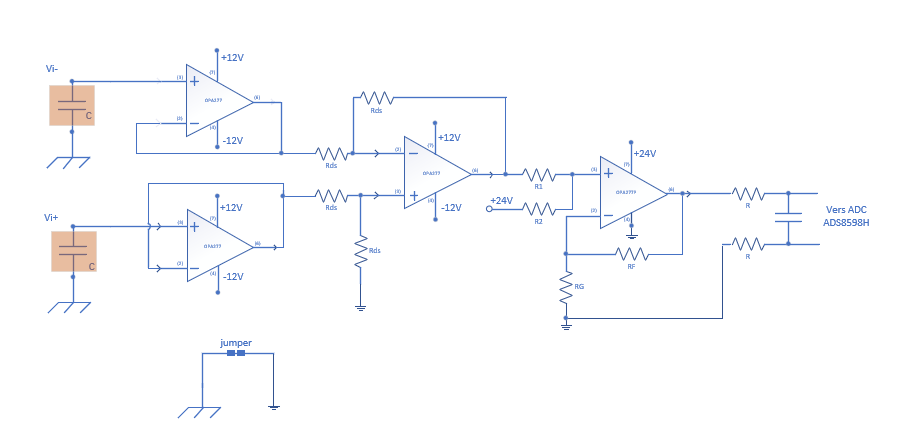
We are using the +-10V input range and we add 3 op amp differential to single ended analog front end (AFE). 

We need this to isolate with a higher impedance the 4 bipolar independant signals  that we need to measure for our application.

We want to calibrate the gain and the offset of the 4 channels of the ADC along with the analog front end together (channel 1, 2, 3 and 5 are used... and Channels 4, 6, 7 and 8 pulled down to the analog ground).

We use the classic linear calibration with Y = mX +b.

The gain "m" we find with the 4 channels is OK and stable all the time. 

To find the AFE+ADC offset of each channels, we shoot a 0V that reads 0.000000133 V with the precision voltmeter. 

With the circuit (AFE + ADC) we read offset values in the range of plus and minus 500 micro volts.

The problem is with the offset. The 4 channels will have a different offset depending on the day and the environment.  

For example, one day we get say [-0.000687 V] offset on a channel 1 and the next day in a similar environment we get  [+0.0001526V].

This is completely in the opposite polarity with the exact same channel.

Question:

Should the ADC offset be the same (or almost the same) all the time?

If yes, what could explain the offset variation that we observe on the prototype?

The variations are in the hundreds of microvolts.

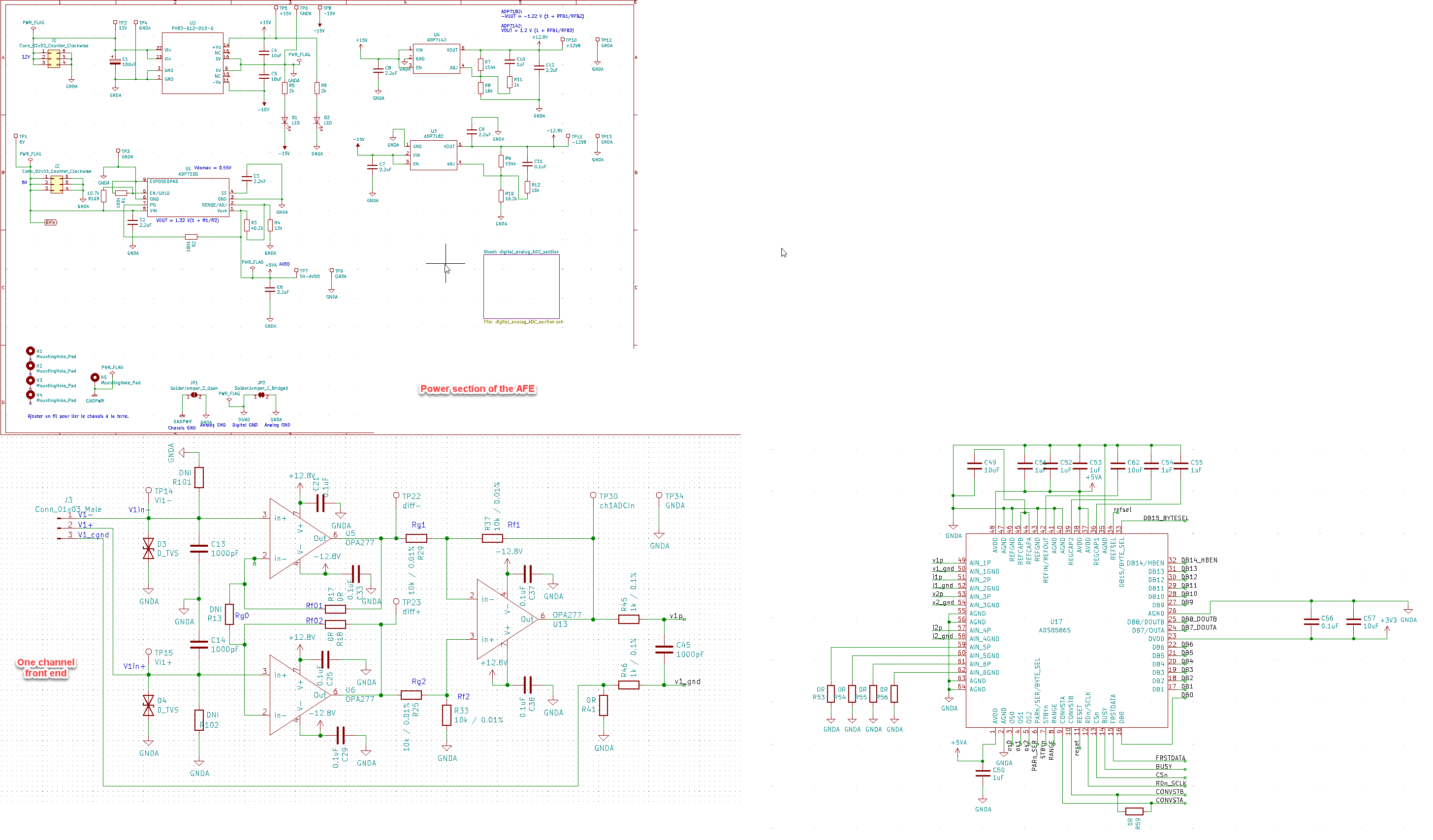
Please find attached an overview of the design (note that the schematic is based on the ADS8586 but we use the ADS8598H that is pin and footprint compatible).

  • Hi Pierre-Luc,

    Can you do a little experiment where you short the ADS8598H input directly at the chip and verify the offset?  You can try power cycling the device a few times to see how consistent the readings are.  From there, you can work you way backward from the ADC pin through your differential to single ended stage to see if there is any variation as you work your way through the input stage back to your actual analog input.  This will help determine if the ADC itself is changing offset or if there is something else in the circuit causing the problem.

  • Hi, thank you for the feedback!

    I identified the problem and it is not because of the ADC. 

    If it could help anyone facing a similar issue, here is our solution:

    We got some offset differences from one test setup to another because in one test setup, the 0V input injected to the AFE+ADC offset was not linked to the chassis ground.  And in the other configuration, the input was connected to the chassis ground.

    Remember that we have differential inputs so in practice, some sensor will not be linked to the system ground.

    Since we measure bipolar DC signals in our application, we are able to hook each differential inpout pins to capacitors that are linked to the chassis ground.  This ensure the system to always have a reference to same ground and the system ground.

    Like this:


    Thank you for the support