This thread has been locked.

If you have a related question, please click the "Ask a related question" button in the top right corner. The newly created question will be automatically linked to this question.

ADS7953: Unable to read out an ADS7953 with a stm32f072 altough it should work in theory

Part Number: ADS7953
Other Parts Discussed in Thread: ISO7741

Hello

I am developing a board to measure many voltages for a student project. On that board are a ADS7953, a ISO7741 and a STM32F072. Now I am at the end of my resources. I can't read anything useful from the ads. Btw I am using an ADS7953 EVAL Board, in case that makes a difference. Im under timepressure so quick inputs are appreciated too.

My setup:

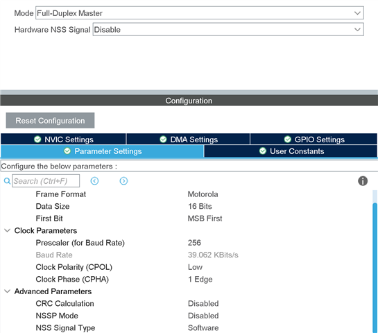
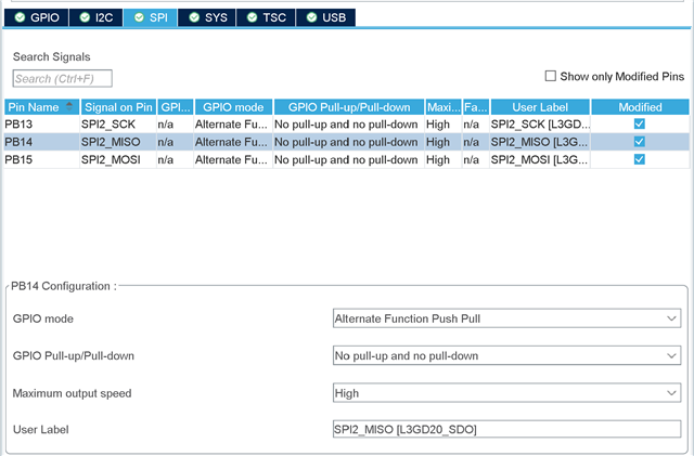
I have set the gpio pins for the spi to highspeed aswell.

I will add my code below but to give a short overview of what it does:

1. Write x8000 to program mode 1
2. Write xFFFF for mode 1 to read all the channels
3. Write x2800 for entering mode 1
4. enter while loop with write all 0 since i dont need to change anything about that. 

below you can see the clock in blue and the MOSI in yellow with the x2800 write. As checked with the datasheet the MOSI is latched on the rising edge, so this should be correct right?


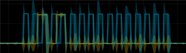
I can add screenshots of the cs line and MISO line too tomorrow. 

the HAL functions used in stm 32 cube ide for the first 3 transmitreceives are the following;

(the writepin is setting the cs line low and high)

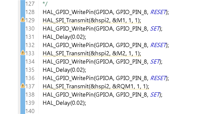
after those the code enters the while loop of the microcontroller. 

I am clueless as to why its not working.

I continue to connect the ADS EVAL Board to its Motherboard to check if i broke the adc but it works fine so the mistake is somewhere else...
Thanks in advance

  • Hi Luca,

    Welcome to our e2e forum and sorry to hear that you are having trouble with the ADS7953!  Including /CS and SDO would be helpful.  Your command sequence sounds correct, what are the warnings you are getting on the SDI writes above (HAL_SPI_Transmit)?  We will not be able to help you debug your STM code, but with more detail on the write and read scope/probe screen shots, we might be able to help pinpoint the issue.  Have you compared your waveforms to those provided when using our EVM and its motherboard?  Do you see any differences?

  • I have actually managed to make it readout channel 15 correctly. But the problem is that it is stuck reading channel 15. Even tho in theory I make it enter Automode 1 before the while loop of the microcontroller. Also i programm the auto mode 1 to read all channels. See code below. Is this a known phenomena? I saw that there is a start up sequence, what should i transmit during that to get to measuer all channels?

  • Have you compared waveforms from our EVM to your setup?

  • Yes and I copied the following startupsequence. It works that way but i dont understand what it is doing. Could you please explain the sequence to me?

    (Automode 1 alle Kanäle)

    0x2810

    0x0000

    0x2810

    0x0000

    0x8000

    0xFFFF (auslesen aller channels)

    0x0000

    0x0000

    0x0000

    0x2C10

  • Hi Luca,

    Let's take a look:

    Mode Control Register for A1 - 0x2810, sets bits 13, 11 (which gives access to bits DI10-00), bit 4 (4 MSBs provide CHX detail)

    Continue operation in selected mode - 0x0000

    Mode Control Register for A1 - 0x2810, same as above, this should not be needed since there were no changes

    Continue operation in selected mode - 0x0000

    Frame 1, Program Register Settings for A1 Mode - 0x8000

    Frame 2, Program Register Settings for A1 Mode - 0xFFFF, all channels selected

    Continue operation in selected mode - 0x0000

    Continue operation in selected mode - 0x0000

    Continue operation in selected mode - 0x0000

    Mode Control Register for A1 - 0x2C10sets bits 13, 11 (which gives access to bits DI10-00), bit 10 (resets CH count) and bit 4 (4 MSBs provide CHX detail)

  • thank you very much. It finally worked together with the ISO7741. I had to implement a pull up on the MISO line and a pulldown on the MOSI line. On the side of the microcontroller I was able to configure it with the chip and inbetween the ADS and the ISO I put two resistances in manually. Is this a usual thing to do or should it work without?

  • Hi Luca,

    I can't think of any reason why you would need the pull-up/down, but inserting series resistance on a switching node is not unusual.  I'm glad to hear that you have it working though!