This thread has been locked.

If you have a related question, please click the "Ask a related question" button in the top right corner. The newly created question will be automatically linked to this question.

ADS1294: Weird Signals

Part Number: ADS1294

Hello dear TI Team,

I am having some difficulties using the ADS1294 chip for measuring EMG signals. A simple custom board is used to measure the signals. I don't even know if the "problem" is a digital or analogue one.

I want to start with the problem. Configuration follows afterwards.

1. Problem

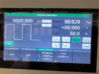
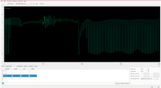
1. I have a square wave signal connected via audio jack on channel 1 (an oscilloscope is also connected)). The other pins are left floating.

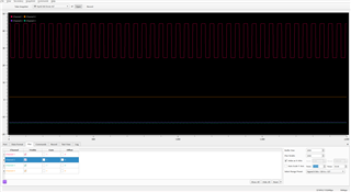
My serial plotter shows the following chart, which has an dc offset but this is also shown on my scope. The amplitude in turn looks very good. Millivolts on y-axis.

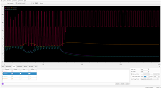
But sometimes this happens and it it seems as if I can influence it, for example by touching the ground connection or the laptop (in that case the weired signals disapear):


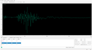
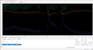
Now let's see the results in the field (without RLD), channel 3 connected to my skin (biceps) via 2 wet electrodes and audio jack:

1. The one muscle contraction can be well detected, as well as the 50HZ power line interference. BUT: I touched ground pin all time, while taking the screenshot.

2. Without touching ground, these weired signals return:

The unconnected, floating channels took weird too:

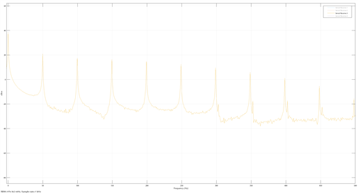
If we check the frquencies there are 50 Hz harmonics?!

If I just leave the channels unconnected:

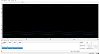
Strangely enough activating the RLD has no affect.

2. Configuration & Code

The ADS1924 is powerd via the microcontroller board, which is powered from USB (Unipolar; VDDA = 5V, VDD = 3.3V). Data is transmitted from ADS1924 to a STM Cortex M7 microcontroller using arduino framework (with mbedOS). On the MCU the bytes are converted to signed integers and the correlating voltage is calculated. Afterwards the samples are transfered to my computer via USB (serial port) and plotted in some serial plotter.

The Configuration of the ADS looks like this:

send_command(SDATAC);

SPI.transfer(WREG | CONFIG1);
delayMicroseconds(5);
SPI.transfer(0x00);
delayMicroseconds(5);
SPI.transfer(0b11000101); // HR mode | multiple readback mode | clock output disabled | 1kSPS
delayMicroseconds(10);

SPI.transfer(WREG | CONFIG2);
delayMicroseconds(5);
SPI.transfer(0x00);
delayMicroseconds(5);
SPI.transfer(0x00); // No test signal
delayMicroseconds(10);

SPI.transfer(WREG | CONFIG3);
delayMicroseconds(5);
SPI.transfer(0x00);
delayMicroseconds(5);
SPI.transfer(0b11101000); // internal ref buf | 4V VREFP | RLDREF internal but buffer pwd
delayMicroseconds(10);
delay(50);

SPI.transfer(WREG | CH1SET);
delayMicroseconds(5);
SPI.transfer(0x03);
delayMicroseconds(5);
SPI.transfer(0b00000000); // 1 -> Normal operation, PGA = 6, Normal Electrode Input
delayMicroseconds(5);
SPI.transfer(0b00000000); // 2
delayMicroseconds(5);
SPI.transfer(0b00000000); // 3
delayMicroseconds(5);
SPI.transfer(0b00000000); // 4
delayMicroseconds(10);
  
send_command(RDATAC);

4. Question

Do you have any idea why this is happening? Is this normal? And why are the signals "pulled to zero" of all things?

Is it due to some weird interference or is just my algorithm/conversion trash/wrong?

How can I stop this and measure clean EMG signals?

Why the RLD has no influence on the signal (CONFIG 3: RLD_MEAS = 0 | RLDREF_INT = 1 | PD_RLD = 1 and RLD electrode connected to skin)?

Thank you very much for any ideas and your help!

Greetings

Benjamin Geiger

  • Hi,

    0. Do you have an ADS1294 evaluation kit/board(EVM)?  Have you ever used EVM to do some preliminary tests e.g. for both ECG and EMG?

    It's highly suggested to use evm to do some preliminary tests and evaluation to get some understanding first.

    -----------------------------------------------

    1. I am not an EMG expert. But, I may suggest some typical methods that could help to troubleshoot noises.

    a. Try Step 0 above first., and then see if you can connect a ECG/EMG simulator to your own system and see how the waveform or noises differ between the two?

    if you are not familiar how a EMG signal usually looks like, it's suggested to start with an ECG simulator first.

    b. Are all the power related sources and components clean and low noise? e.g. battery power or not? 50/60 Main power connected to product and/or computer or not? How is the product's grounding topology if there are chassis and/or enclosures. All these need to be tied and tests and could affect the signal quality&integrity.

    c. definitely try and test and compare the RLD electrodes and its related switches. Products designers&developers will need to do experimetns&tests&data collection&analysis to find the appropriate RLD related settings with respect to the products(i.e. including, cables, wires, electrodes, patches, gels, enclosure, skin textures, etc).

    2. In addition to the steps from 0 and 1.
        Maybe you could configure your ADS to
        a. Internal Short and
        b. Internal Tests signals first and
        remove all the input connections and to see how the internal noise floor and internal test signals look like. Expect them to be clean. If not clean, then you will need to figure out the noises sources by looking&analyzing these internal short and internal tests waveforms. Start with lower gain and slow SPS, then move to higher gain and higher SPS.

    3. You may compare your schematic design with the ADS1294EVM(available on TI webiste) to see if there are any significant differences or concerns.
         if you are using customer PCBA, maybe check to make sure all the analog related power and signals are far away from digital signal lines.

    Thanks

  • Hi,

    thank you very much for your fast and very detailed answer. I appreciate it very much.

    In fact i should do some preliminary test with the EVM, which I did not. I'll get one and do some tests and comparisons to the custom PCBA.

    After posting here I thought everything through again and came to a quite simple conclusion / amateurish mistake, which I'll try to confirm next week:

    - Due to the not connected / not active RLD the common mode voltage is floating and unknown. In times it exceeds the absolut limits of the ADS, signals lines drop to zero. Touching ground e.g. influences common mode voltage and pulls the input signals in the allowed range.

    -> Experiments with RLD & single ended vs. differential inputs & AC coupling should provide further insight.

    I'll keep you posted and get back to you when more specific questions arise.

    Greetings

    Benjamin