Because of the Thanksgiving holiday in the U.S., TI E2E™ design support forum responses may be delayed from November 25 through December 2. Thank you for your patience.

This thread has been locked.

If you have a related question, please click the "Ask a related question" button in the top right corner. The newly created question will be automatically linked to this question.

DAC6578: no output on Vout pin

Part Number: DAC6578

Good afternoon,

Overall question: Do I need to map pins 1 or 8 to anything? Do i need to provide the DAC with any other commands to possibly shift its input from the data buffer to the register? Do I need to further power on the DACs beyond just applying a voltage to AVDD and connecting GND to the appropriate pins?

I'm wondering whether there are additional steps i need to take IOT have the DAC6578 operate correctly. I'm following along with Ex1 on p40 of the data sheet

-ive verified that each of the necessary commands is making it to the I2C bus and the dac is acknowledging the commands (i2c SDA pulled low at 9th bit position)

-I am using the TSSOP package.

-i have 3v3 applied to pin 3 (AVDD) 

-pin 1 (LDACn) and pin 8 (Vrefin) are floating. 

My understanding is that i will automatically see 1.65V on pin4 (Vout_A) since i am writing midscale to register A (exactly like the above example) and my voltage range is from 0 to 3v3. are my expectations off? 

as an aside, what does it mead to "load a dac"? 

  • Hi James,

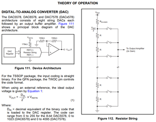
    Vrefin cannot be left floating. The DAC uses the reference to set the output. 

    Figure 111, and 112 show how Vrefin is used internally:

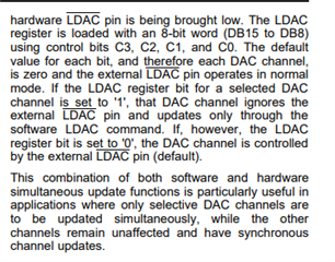
    LDAC should also not be left loading. LDAC is a pin that is used to "load the DAC" with the contents DAC register. The "DAC" is the internal resistor string in the device that is shown in figure 112. The DAC switches are loaded with the data in the DAC register to set the output. 

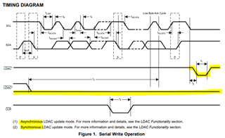
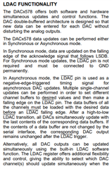
    In Synchronous mode, the LDAC is held low and the DAC is loaded with the contents of the DAC register when the I2C write is finished. 

    In Asynchronous mode, the LDAC is held high during the I2C sequence and the DAC is loaded with the contents of the DAC register when LDAC is pulled low. 

    Page 38 of the datasheet explains the two modes. You can use the LDAC in SW, HW or not at all, but either way the pin needs to be set accordingly. 

    Please share a schematic so I can verify the rest of the connections. No inputs should be left floating. Unused DAC outputs can be left floating. 

    Best,

    Katlynne Jones

  • sick answer. thank you...i got it working :)

  • Hi James, 

    Great! Please reach out if you run into any more trouble.

    Best,

    Katlynne