This thread has been locked.

If you have a related question, please click the "Ask a related question" button in the top right corner. The newly created question will be automatically linked to this question.

DDC264: Configuration Register Write and Read Operations

Part Number: DDC264

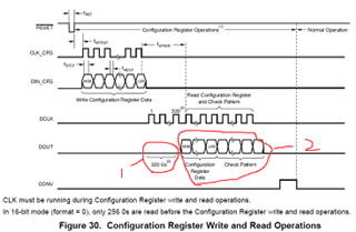
  What is the 320 0s mean in the circle one?

What is the readback data strructure after Configuration Register Data Write and 320 DCLK Clock Pulses Provied in the circle two?

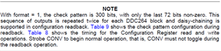
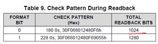
According to the NOTE and Table 9,16bits Configuration Resgister Data,then 4-bit revision ID,and 300bits the check pattern,how can it has 1024 TOTAL READBACK BITS with format = 0 ? 

And what is the 4-bit revision ID,how can i set them?

Thanks for your help!

  • Hi,

    We need more time to get back to you. Hopefully around 5/18.

    Thanks

  • Hi,

    Please take a look of datasheet page 21

    Optional readback of the Configuration Register is available immediately after the write sequence. During readback, 320 '0's, then the 16-bit configuration data followed by a 4-bit revision ID and the check pattern are shifted out on the DOUT pin on the rising edge of DCLK. The check pattern can be used to check or verify the DOUT functionality.

    320 of 0s

    With format 0 selected, 16 bits/channel * 64 channels = 1024 bits

    Thanks

  • Get it.

    "Optional readback of the Configuration Register is available immediately after the write sequence",

    NOTE show "This sequence of outputs is repeated twice for each DDC264 block",

    Figure 30 show "In 16-bit mode (format = 0), only 256 0s are read before the Configuration Register write and read operations",

    so i can get the 16-bit configuration data followed by a 4-bit revision ID and the 236-bit check pattern twice 256*2 = 512 bits with format 0 selected after the write sequence immediately during the Configuration Register Operations,right?

    And i can get 1024 bits during the Normal Operation,right?

    but what the 4-bit revision is?

    Thanks for your reply

  • Revision ID is hardcoded in the device. User is not allowed to access or change.

  • Thanks for your reply.And what about "get the 16-bit configuration data followed by a 4-bit revision ID and the 236-bit check pattern twice 256*2 = 512 bits with format 0 selected after the write sequence immediately during the Configuration Register Operations" and "get 1024 bits during the Normal Operation",is it correct?

  • What do you mean by ' the 236-bit check pattern twice 256*2 = 512 bits"?
    --------------------------------------------------------------
    Refer to Figure 30's DCLK and DOUT,
    if format = 0, there are 256 '0's
    if format = 1, there are 320 '0's
    on DOUT before the configuration register data.

    "then the 16-bit configuration data
    followed by a 4-bit revision ID
    and the check pattern
    are shifted out on the DOUT pin on the rising edge of DCLK." , where the check pattern is format bit dependent, as listed in Table 9.

    "Strobe CONV to begin normal operation, that is, CONV must not toggle during the readback operation." So, Normal operation won't start until the CONV's falling edge.

    Thanks