Other Parts Discussed in Thread: AFE781H1, USB2ANY,
I am working with the TI AFE781H1 Hart Modem.
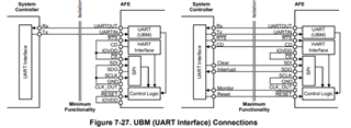
I am trying to write to the registers to setup the modem to be used in Uart Break Mode and enable the HART.
This means first setting the REG_MODE bit to 1 in register UBM, and then setting the HART_EN bit to 1 in register MODEM_CFG.
I am looking for confirmation that I am sending the correct sequence of bytes and with the correct timing.
Here is my sequence:
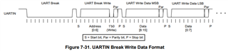
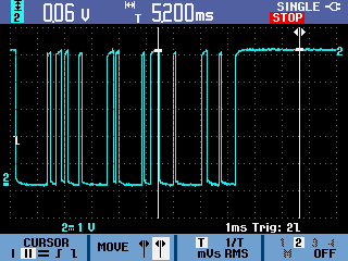
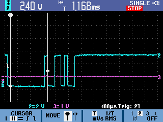
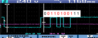
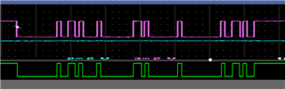
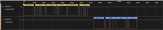
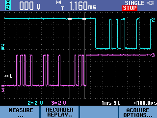
1. Send a low signal (Break) for 11 bit periods (1.18ms).
2. The signal then goes high for 1.16ms while re-configuring the processor Tx pin for Uart operation. The baud rate is set for 9600.
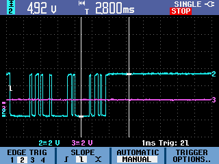
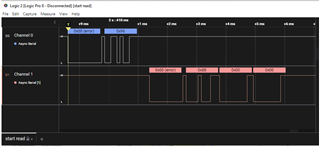
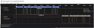
3. Send 3 bytes for register UBM (0x2C, 0x00, 0x01).
4. Send 3 bytes for register MODEM_CFG (0x1C, 0x00, 0x08).
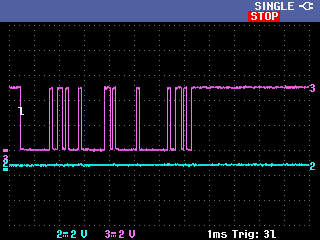
After executing this sequence, and with my Hart Master connected, I am not seeing the Carrier Detect (CD) signal changing at all.
One of my main questions is, is the delay between the Break signal (11 bit periods) and the first Uart byte too long?
Do you have any application notes besides what is in the data sheet that describes how this sequence should be done?