Other Parts Discussed in Thread: DAC38RF82, DAC39J84
Hi All,
I am driving DAC39J84EVM using an external clock (with TSW14J56 Rev E board as the generator and using HSDC Pro for software support.) For this purpose, I am providing a 1000 MHz external clock. I want DAC to operate at a higher clock, but have some conceptual doubts regarding this:
1) Are the external clock frequency provided ( say 1GHz ) and DAC data input rate field on the DAC GUI same things when operating in external Clock mode ? Also, is DAC data output rate field similar to the DAC sampling rate. Basically, I wanted to know how are the DAC sampling rate and the external clock provided is related ? A simple example to understand these might be really helpful.
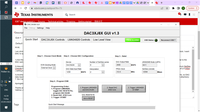
2) Assuming the external clock is related to the DAC sampling rate, it seems the maximum DAC data input rate or the clocking frequency we can go with is 1.25 GSps (or 1.25 GHz) owing to the maximum SerDes Linerate limit and the maximum DAC Output rate limit. As, the maximum sampling rate is 2.8 GSps for this DAC, the maximum we can achieve using these settings seems like a DAC data output rate of 2.5 GSps ( setting interpolation 2 and Ser Des lanes as 8) ( screenshot attached) . Is that the maximum we can achieve and not 2.8 GSps? If yes, how can we achieve the stated 2.8 GSps sampling rate?
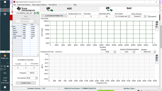
3) Another thing I wanted to understand is why the bandwidth of DAC is half of the DAC data output rate or the sampling rate and how are they related (For example if we take an external clock of 1 GHz, so DAC data input/output rate is 1 GSps, assuming interpolation as 1. Then when we enter data rate as 1GHz on HSDC Pro software, we get the bandwidth of DAC as 500 M on the FFT diagram ( screenshot attached)) ? Do I need to change some settings to access full bandwidth as the external clock provided?
Apologies for such long queries, but these will contribute a long way towards my understanding.
Thanks and Regards,
Vaibhav Jain.