This thread has been locked.

If you have a related question, please click the "Ask a related question" button in the top right corner. The newly created question will be automatically linked to this question.

AFE7222: AFE7222 integration with TRF371109 and TRF371135

Part Number: AFE7222
Other Parts Discussed in Thread: TRF371109, TRF371135, , TRF370333

I have a query regarding the connection of IQ outputs from TRF371109 and TRF371135 to form a single IQ channel (one differential I and one differential Q) for sampling using the AFE7222.


Can anyone please provide instructions or a recommended configuration for connecting the IQ outputs of these devices to the IQ input of the AFE7222? I am specifically seeking guidance on circuitry, interface considerations, and required steps.


Additionally, if there are any relevant resources such as application notes or reference designs, I would greatly appreciate receiving them.


Thank you for your attention to this matter. I look forward to your prompt response.

  • Mohammad:

    The interface to the ADC, by design, is actually quite easy.  The TRF3711xx was designed to interface to a variety of ADCs.  Below is a snapshot of the input interface schematic from the AFE7222 EVM.  If the picture does not come through well you can access the design files on ti.com.  Most of the components can be eliminated.  There is no need for the baluns, AC coupling, or the VCM injection voltage resistors.  You can keep the series 10 ohm resistors and the final RCR filter is optional.  That's it.  Essentially directly hook up the differential outputs of the TRF3711 to the differential inputs of the ADC.  Note, the TRF3711 wants to drive a high impedance load, so do not add any 50 or 100 ohm terminations.

    The TRF3711 has a unique feature for setting the common mode voltage, and the AFE7222 has a common mode voltage output.  Connect the common mode voltage output from the AFE7222 to pin 24 of the TRF3711 (VCM input).  This will translate that common mode voltage to the differential outputs.

    On the TX side, you can consider using the TRF370333 quadrature modulator to interface with the AFE7222 DAC.

    --RJH

  • Hello RJ Hopper, 

    Thanks for the clarification, that was very useful and I will make sure to follow this in the design process. However, it did not answer my original question. How to connect both TRF371109 and TRF371135 at the same time to cover a wider frequency range? Is there a recommended switching mechanism or circuit that doesn't affect the signal quality?

    Thanks, 

    Mohammad 

  • Ahh, I did not catch that you want to connect up both simultaneously.  Note, the TRF3711 family will operate outside of the published frequency ranges, it is just that the gain response will degrade.

    If you want to hook up both simultaneously, an RF switch matrix could work.  I am thinking that each output (eight in total) has an RF switch that switches between short and open circuit.  The outputs are effectively routed in parallel, but the RF switch keeps changes the outputs from the unwanted device into an open.  Given that the frequencies will be below 15 MHz, the routing will be forgiving.  Conceivably, because the frequencies are low, one of TI's load switches or muxes could be used for this purpose; however, I have never tested those for anything other than DC or GPIO switching.

    In this scenario, you have to chose which device is being used and that implies an RF switch on the input as well.  

    --RJH

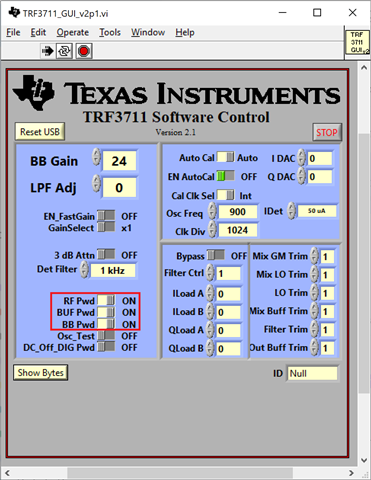
  • I was thinking of using an SPDT switch on each connection as well as enabling the power-down option using software on the unused demodulator (see image below). BTW, both the TRF371109 and the TRF371135 have a Baseband low-pass filter cutoff frequency when on bypass mode of 30 MHz. This will make the selection of the switch as well as the routing of the traces more critical.