Other Parts Discussed in Thread: AMC3301
Hello, all.
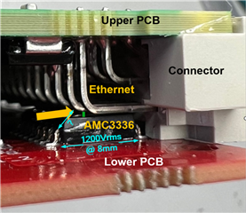
I have a prototype application where the AMC3336DWER is closely coupled to some industrial connector leads with 100BASE-TX Ethernet signals.
In Fig. 01 you can see the leads close to the AMC3336 package top face (< 1mm), but they don't touch each other.
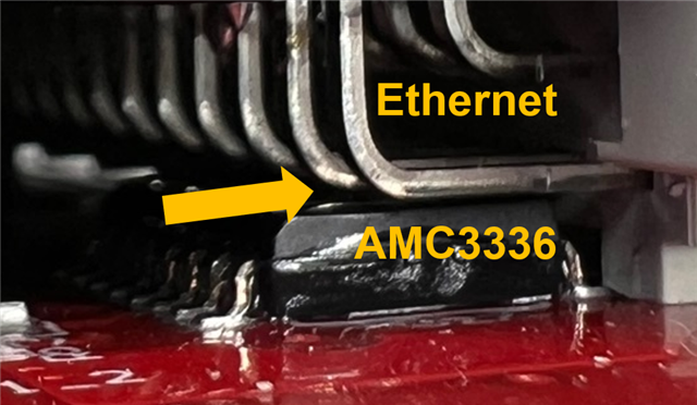 Fig. 01
While testing the Ethernet port through the industrial connector according to EN 55032 (CISPR 22) conducted emissions specs (100kHz to 30MHz BW), there is a ~400kHz noise when a 10MHz, 3.3V, 50% duty cycle clock signal is applied to AMC3336 CLKIN input by an MCU.
Fig. 02 shows the results with no clock applied to CLKIN input. The CLKIN voltage level is kept low (0.02V) by the MCU, despite the CLKIN has a ~1.5MΩ pull-down internal resistor (MCU output is low, not high impedance). No outstanding noise is seen.
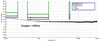
Fig. 03 shows the results with the 10MHz, 3.3V, 50% duty cycle clock applied to CLKIN input. You can see 411kHz peak followed by its 2nd, 3rd etc. harmonics.
I tested two prototype samples, and the second one showed a 424kHz, with similar behavior.
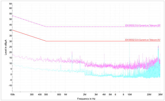 Fig. 02
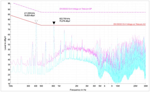 Fig. 03
My theory is the AMC3336 has a chopper circuit, or a similar circuit, running at ~400kHz in it, but not documented in the datasheet, and the noise created by the chopper was coupled to the industrial connector leads though radiated emissions, due to the very close proximity, then this coupled noise created the conducted emissions seen on the test.
This related post [ 1059315 ] made me think there is a chopper circuit in the AMC3336 too.
The available literature related to EMC for the AMC3301 family only covers CISPR 11 and CISPR 25 specs (30MHz to 1GHz BW) radiated emissions, outside my target spectrum (100kHz to 30MHz BW, conducted emissions).
My AMC3336 design is according to the [ AMC3336 ] datasheet and the [ AMC3336EVM ] schematics. However, the PCB layout isn't strictly following the layout recommendations, possibly increasing the radiated emissions.
I would like to confirm if there is anything inside the AMC3336 that could create the noise I have described, before I redesign my PCB.
I appreciate your help here.


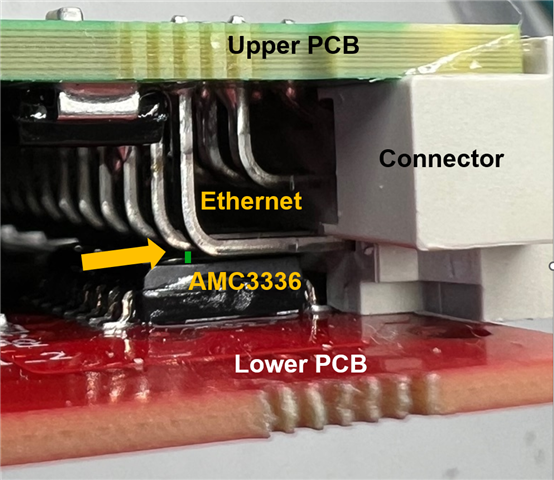 Fig. 04