This thread has been locked.
If you have a related question, please click the "Ask a related question" button in the top right corner. The newly created question will be automatically linked to this question.
Hi,
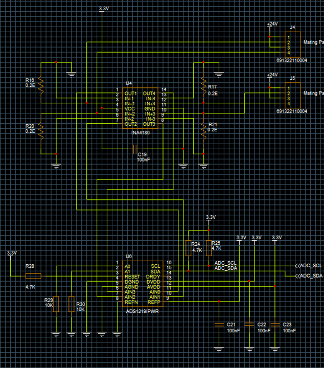
When using ADS1219, each channel of this IC is giving different current readings. The values are below.
Channel 1 |
Channel 2 |
Channel 3 |
Channel 4 |
6.505 |
6.523 |
6.441 |
6.436 |
Is this normal or any other way to achieve 0.01 accuracy with ADS1219?
Hi Aswin Kumar,
The ADS1219 is an ADC that gives a result code relative to voltage reference. This means that the ADC is not converting to current but rather converting to a voltage. You are then making a calculation to current based on Ohm's Law.
In the case you have presented, you have made the calculation, but I have little understanding as to the configuration of the ADC (gain, data rate, reference, etc.) or the value or resistance you are using to determine the current. Also, this is a single measurement and I do not know the value of current provided, if there is noise in the input path and the value of the current shunt or its precision.
So I really need to know more information before I can be of much help as you are giving me a single point measurement without knowing precisely how you are making your measurement. Please send me your schematic, ADS1219 configuration and details on how you are conducting these tests.
Best regards,
Bob B
Hi, Sorry for the delayed reply. Here I have attached the schematics. Please check it. For VRef I'm using Internal reference. Which is not updated in the shared schematics..
Hi Aswin Kumar,
Could you also send me the configuration register settings that you are using for the ADS1219? I would also like to know which version of the INA4180 that you are using with respect to gain. It would also be helpful to know the accuracy and part number of the shunts you are using. Could you also explain how you are making the current measurements for comparison (what is your source and how are you determining the correct value for current)?
Thanks,
Bob B
Hi Bob,
As discussed, Please check the details provided below.
Shunt Resistor PN : KDV12DR200ET
Current sense IC PN: INA4180A3QPWRQ1
ADS1219 configuration:
Conversion mode : Single-shot conversion mode,
Gain configuration : setting Gain=1,
Data rate : 20 SPS,
Voltage reference selection : Internal reference voltage of 2.048V
Current finding calculation:
External reference voltage = 2048mV.
Code range = 0x7FFFFF ( (2^23)-1) .
Current gain = 100V/V as per INA4180 current sensor.
Shunt resistor =0.2 ohm.
ADC Voltage =( ADC value * External reference voltage)
Voltage = ADC Voltage / Current gain. # Dividing ADC voltage with Current gain to reduce amplification.
Current = Voltage / Shunt resistor. # Dividing Voltage with Shunt resistor to find current.
Hi Aswin Kumar,
You need to consider your total unadjusted error (TUE) for your system. It will not be possible to get channel to channel consistency without calibration. The shunts alone are 0.5% accuracy and the INA can have gain error up to 1%. This does not include any other issue as it may relate to noise or ADC error. so given this information it would appear (not knowing the specific current being provided) that the measurements you have taken are within the expected range of values.
As to the measurement itself, you are making a single-point measurement and comparing. You need to also consider the accuracy of your source and if there is any noise affecting your measurement. Taking multiple measurements in a contiguous and continuous way (which means continuous conversion and not missing any conversion data) and collecting at least 128 samples for each input channel will help determine if external noise is a factor. Your circuit shows no low-pass RC input filtering which would be beneficial for reducing noise and preventing any aliasing.
Given your input circuit and the components involved you are within the expected operation of the system.
Best regards,
Bob B