This thread has been locked.

If you have a related question, please click the "Ask a related question" button in the top right corner. The newly created question will be automatically linked to this question.

ADS1299-4: Queries regarding the Working of ADS1299-4PAGR AFE

Part Number: ADS1299-4
Other Parts Discussed in Thread: ADS1299

Hi Team,

We are working on capturing the EEG signals. We chosen ADS1299-4PAGR as the AFE. 
We have some queries regarding the chip

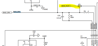
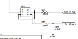
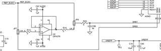
1. Kindly provide some ideas on the bias pins and SRB pins?

2. Can we use a low noise pre amplifier before AFE to amplify the signals from the electrode?

3. Regarding the AVDD anbd AVSS- i have 2 options like AVDD 5V & AVSS 0V or AVDD 2.5V & AVSS -2.5V. Which is preferred? Is there any posibilities for the EEG signals to be negative especially in sequential montage?

4. Kindly provide reference schematics or Evaluation board design for the  AFE ADS1299-4PAGR

  • Hi 

    1. 

    We are not EEG experts, and usually, typically, there are at least two or more topology(montage) customers use, so customers need to make decision.

    For starter, one could take a look of the ADS1299 datasheet-  

    Figure 72. Example Schematic Using the ADS1299 in an EEG Data Acquisition Application, Sequential Montage

    Figure 73. Example Schematic Using the ADS1299 in an EEG Data Acquisition Application, Referential Montage

    to first decide what topology(montage) or others they want to use.

    Based on the interaction one/application wants those electrodes to be, then one could decide how to connect.

    BIAS_ELEC came from BIAS_DRV,

    "The BIAS_DRV can be used as the BIAS_ELEC signal by installing JP1 (1-2)."

    so you can install jumper in JP1 so that the center pin of JP1 is short with the BIAS_ELEC pin.

    And, then jump wire/cable from one of JP25's 2,4,5 to where you think to be or want to put BIAS electrode.


    --------------------------------------------------------

    Regarding to REF_ELEC, you can connect the REF_ELEC electrode to JP25 pin 6,

    and then it's user's option to decide whether to use the following OpAmp as voltage follower along the way-

    if want to use OpAmp as voltage follower and want to have reference node goes to SRB1, install

    JP7 to short center pin to REF_ELEC

    and

    JP8 to short center pin with R14

    --------------------------------------------------

    If don't want to use OpAmp as voltage follower and want to have reference node 

    goes to SRB1 - 

    uninstall JP7

    and

    install JP8 to short center pin with REF_ELEC

    -

    or 

    -

    goes to SRB2 -

    short JP7 pin 1 and 3

    uninstall JP8

    ----------------------------

    2. Will you need to use Lead off detection feature/function? If yes, not recommended using PreAmp.


    3. No preference. it's customers' choice/selection.

    4. https://www.ti.com/lit/ug/slau443b/slau443b.pdf?ts=1695171175403&ref_url=https%253A%252F%252Fwww.google.com%252F

    Starting page 50.

    Thanks.