This thread has been locked.

If you have a related question, please click the "Ask a related question" button in the top right corner. The newly created question will be automatically linked to this question.

ADC12DJ5200SEEVM: Cannot capture appreciate data on "High Speed Data Converter Pro"(HSDC) with "TSW14J57EVM" and "ADC12DJ500SE EVM"

Part Number: ADC12DJ5200SEEVM
Other Parts Discussed in Thread: TSW14J57EVM, ADC12DJ5200SE

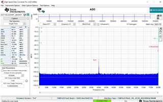
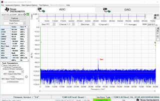
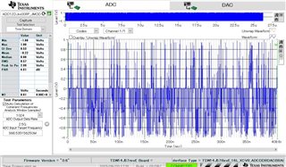
We couldn't capture appreciate data on "High Speed Data Converter Pro"(HSDC) with "TSW14J57EVM" and "ADC12DJ500SE EVM". Concretely, we input a 10MHz 1Vp-p sine wave but capture the waveform shown in the attached figure.
Could you please tell us some tips or suggestion on how to solve this problem? We describe the settings below.

TSW14J57EVM settings on HSDC
FPGA firmware: TSW14J57RevE_16L_XCVR_ADCBRAMDACDDR.rbf
ADC files: ADC12DJxx00RF_JMODE0.ini
ADC Output Data Rate: 2.5GHz
ADC Input Target Frequency: 998.53...MHz*
*We check "Auto Calculation of Coherent Frequencies".

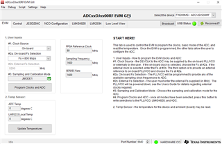
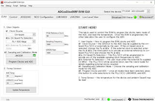
ADC12DJ500SE EVM settings on ADCxxDJxx00RF EVM GUI
"EVM" tab >> 1. User Inputs
#1 Clock Source: On-board *
#2 On-board Fs Selection: Fs = 5200Msps
#3 Sampling and Calibration Mode: JMODE0
*We fixed the part of circuits shown in Fig7-5 of "slau640b.pdf".

  • Hello,

    Can you clarify that you wish to use the ADC in single channel interleaved mode at its max sampling rate? If this is the case you cannot use jmode 0, it does not have enough serdes lanes to support the output data rate of the adc at its max sampling frequency. In jmode 0 your max sampling frequency will be 4290 MHz. So this would certainly be causing issues in your capture. To remedy I would recommend using JMODE 1 this will allow you to sample at the max frequency of 5.2GHz. Some changes you need to make in HSDC pro would be the "ADC Output data rate" you must set this to your sampling frequency in the case of JMODE 1 fs=5.2GHz your output data rate will be 5.2GHz * 2 = 10.4GHz. Additionally The auto calculation of coherent frequencies feature will just help you calculate a coherent frequency to input to the ADC, it does not have any effect on the plotting of the signal.

    Best,

    Eric

  • Hello Eric,

    Thank you for the reply.

    We tried JMODE 1 or JMODE 0 with slower output data rate (ex. 800Msps), but captured the same waveforms.

    So I would ask some questions.

    1. In ADC12DJ5200SE datasheet,  "Analog input range (–3 dB): 2 to 6.3 GH" is described. Can't the device capture 10MHz sine wave data?

    2. We input no signal, but still capture the same waveform. Should we set other configrations of FPGA and ADC? Or may the device input crushed?

    Could you please tell us any hint about this problem?

    Sincerely,

    Masaki

  • Hi,

    Yes the ADC12DJ5200 SE has an analog input bandwidth of 2GHz-6.3GHz, this has to do with the fact that it is a single ended input oppose to a differential, If you use the ADC12DJ5200 RF, which is the differential version of the same chip you won't have this limitation.

    Can you clarify how you are programming the device, does it match what I show below? If so can you verify that all the clocks sent to the FPGA are correct?

    Also in HSDC pro you will have to set your output data rate to the correct value in the instance you describe above you are setting Fs=800MHz for the evm but the ADC is actually sampling at twice that speed because it is interleaving the adc cores internally so your output data rate would be 1.6G, not 800MHz. If it is all setup correctly you should be able to get a capture similar to mine I have shared, there is no input to the adc here it is just the noise floor.

    Best,

    Eric 

  • Hello Eric,

    Thank you for your suggestions. We may set the wrong condition about ADC input target frequency.

    I captured data with no input on the configrations you showed above, and get the follow waveform.

    Is this the expected waveform?

    Sincerely,

    Masaki

  • Yes, everything looks like it is working correctly. that looks like a really clean noise floor, that on spur you are seeing is the interleaving spur that is to be expected.

    Best,

    Eric