This thread has been locked.

If you have a related question, please click the "Ask a related question" button in the top right corner. The newly created question will be automatically linked to this question.

ADS127L11EVM-PDK: I cannot get the board to work

Part Number: ADS127L11EVM-PDK

Hi,

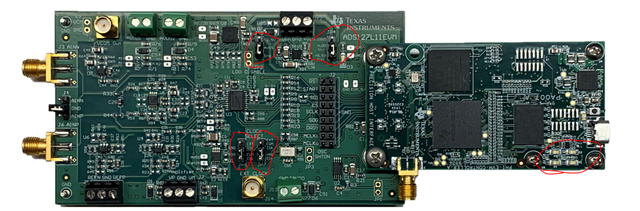
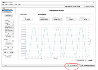
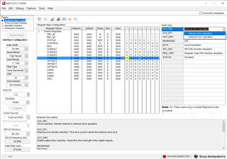
We have  purchased the EVM board and cannot get it to work. I can read and write the registers, but when I do a capture,

the window just stays there and nothing happens.

I put a scope on the lines and can see the SPI data, but nothing happens on the start pin

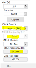
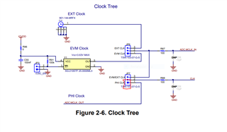
(I was expecting a pulse to start reading). I tried changing the jumpers for the clock, but no luck.

Any ideas what could be wrong?

Thanks,

Owen.

  • Hello Owen,

    Can you confirm that you have the latest version of the board as shown in the below picture?  Assuming you have the latest version, there are a total of 4 shunts that need installed on the board headers (you already adjusted one of them for the clocks).  The default positions are needed in order for the board to work with the default GUI settings.

    Also, it is important that the screws attaching the data capture card (PHI) to the main board are installed.  This connector does not always fully seat properly without the screws.

    If the GUI and PHI power up properly, you should see the Green LED's blinking on the PHI board, and a constant 'ON' green LED on the ADS127L11EVM board.  If the PHI board properly read the EEPROM on the main board, you should also see the GUI HW Connected indicator GREEN.

    Also, the default configuration of the EVM uses the PHI 24MHz oscillator, and the GUI should be configured as shown below.

    These boards are fully tested during the manufacturing process, but it is possible something has been damaged at some point.

    Regards,
    Keith Nicholas
    Precision ADC Applications

  • Hi Keith,

    Thanks for the reply. I checked all the above settings, I have all three LEDS, two are flashing.

    I have the HW Connected, checked the jumpers and I can read and write the registers.

    The Capture does not work though, I guess the board must have been damaged.

    Much appreciated,

    Owen,

  • Hi Owen,

    O.K., the SPI and power supplies should be working if you can read and write to internal registers.  If the main clock is not present, then this could explain the behavior of the board.  You would need to probe the CLK input pin of the ADC and with default GUI settings, you should see a 24MHz square wave.  If not present, then you could work through the board schematics to figure out where the fault occurs.

    Probing pin 2 or pin 1 of JP7, you should see the 24MHz clock.

    Another option that does not require hardware debug is to enable the internal oscillator.  Go to the Register Map page and change the MSB in the CONFIG4 register to internal oscillator.

    Or, you may decide to get another EVM kit in case there is something wrong with the hardware.

    Regards,
    Keith