This thread has been locked.

If you have a related question, please click the "Ask a related question" button in the top right corner. The newly created question will be automatically linked to this question.

ADS8684: ADS8684 : range selection issue

Part Number: ADS8684
Other Parts Discussed in Thread: ADS8688

Hi,

I'm using the ads8684 adc with a Stm32f7 microcontroller and I can read the voltage with SPI communication on each channel (the values I get are correct)

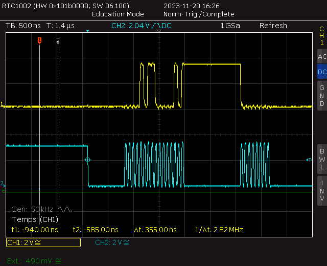
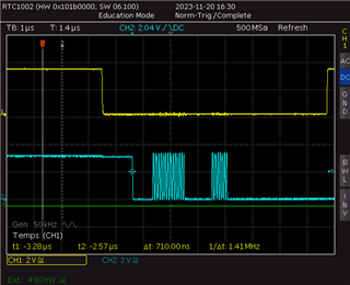
but I cannot change the range. It stays at +-10V. I checked with an oscilloscope and the timing looks good (see the two screenshots)

Can anyone help me with this issue? Thanks.

this is the data sent to ads8684 with the clockthis is the SCLK line with CS

  • Hello Vincent,

    Thank you for your post.

    Which channels are you trying to configure and what is the gain setting you're attempting to write? Is VREF the default 4.096 V internal reference?

    Please share the sequence of hexadecimal commands you are sending to the device to complete the register write operation and we can review it after the Thanksgiving Holiday.

    Regards,

    Ryan

  • Hello Ryan, Thanks for your answer. Yes the VREF is at 4.096 volts. As I said, when I apply voltage on a channel, I can measure it and it gives the correct value (when I send command 0xA000).

    The bytes I'm sending to change the range are:

    byte 1 : 0x0B, byte 2 : 0x05, byte 3 : 0x00.

    These bytes are the first bytes that I'm sending when the device is powered on and they are sent after a few milliseconds (time for the uC to initialise all peripherals).

    best regards,

    Vincent

  • Hi Ryan,

    Did you find something about this issue? I haven't heard you for a while.

    Best regards,

    Vincent

  • Hello Vincent - apologies for the delay and thanks for the reminder. Admittedly I lost this thread while catching up from the holidays.

    The command byte sequence looks correct for changing the range of CH0 to the 0 to 2.5*VREF range. Can you try reading back the same register address (05h) in the next frame following the register write command? 

    Regards,

    Ryan

  • Hi ryan, I tried to read the register and I get value 0x00 (default value according to the datasheet).

    I sent those bytes to the chip :  0x0A, 0x00, 0x00

    Best regards,

    Vincent

  • UPDATE : After reducing the speed of the SPI down to 13.5 MBits/s, I could change the range on channels 1 to 3 but not channel 0. I'll take a look in my code to see if I can find anything arround this issue.

    Best regards,

    Vincent

  • UPDATE #2 : After checking each channel individually, I can select any range on channel 2 and 3 but I cannot select the ranges

    +-2.5v and 0-5v on channel 0

    0-10v and 0-5v on channel 1.

    I checked the range registers and the value is correctly written.

  • Hi Vincent,

    Ryan is on vacation now, so I will support you. The maximum SCLK frequency supported by ADS8688 is 17MHz. The command format is same for setting all ranges on all channels. Can you please let me know what code you got for the ranges/channels you listed above and also what your input is? Also, can you try another ADC device?

    Regards,

    Dale