This thread has been locked.

If you have a related question, please click the "Ask a related question" button in the top right corner. The newly created question will be automatically linked to this question.

TSC2017: Test method of IEC standard 61000-4-2

Part Number: TSC2017
Other Parts Discussed in Thread: STRIKE

Hi all,

I would like to know test method based on  IEC 61000-4-2.

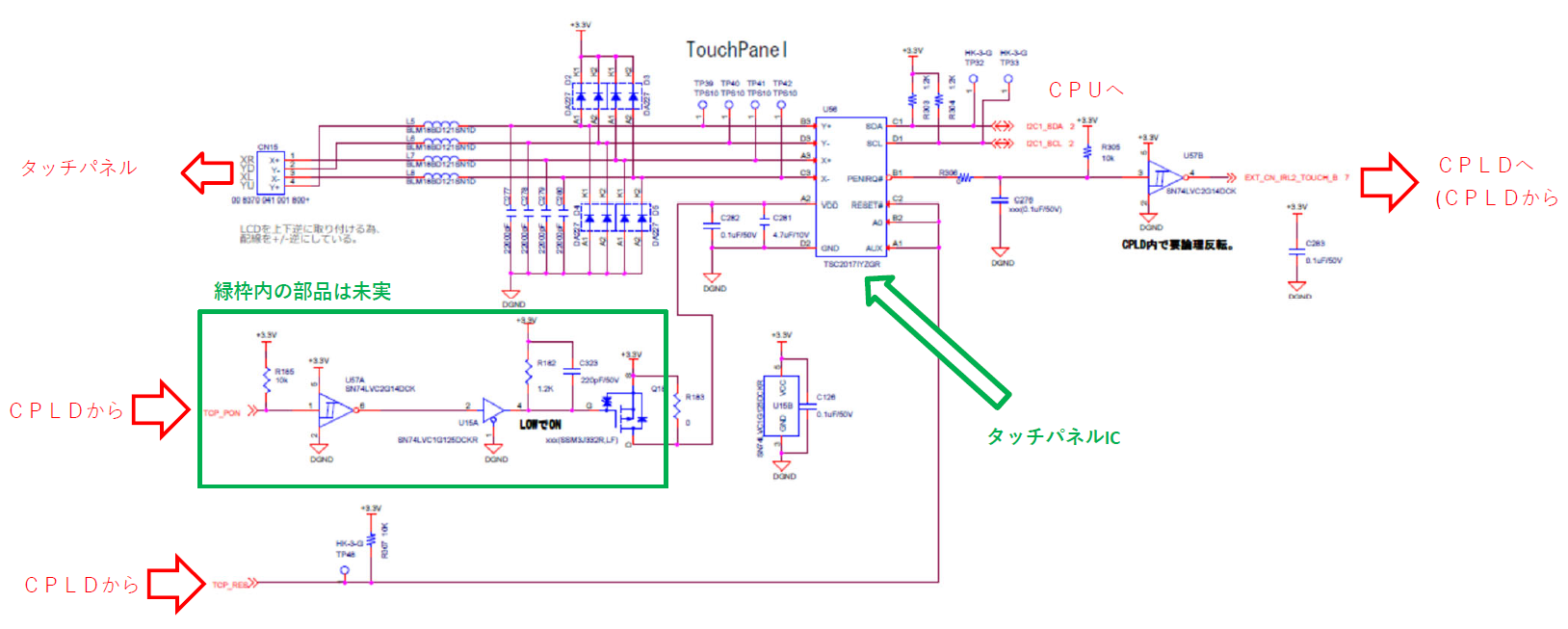
My customer ran ESD test of ±8kV in-air discharge on the finished product.

As a results, the touch screen froze.

I would like to ask you about the details of the test of TI because I want to compare ESD test with the TI test method.

Could you tell me anything about the circuit configuration and the details of the test?

Best Regards.

Ryusuke

  • Generally this is done with the ESD Gun and either the gun is placed in contact with the pin or at a small distance from the pin. The TSC2017 Passes the below test

    ±25kV Air Gap Discharge 

    ±15kV Contact Discharge

    https://youtu.be/AcP8N8x2wFQ?si=l-gHrjvd8dCaDntc

  • Hi Sanjay,

    Do you conduct ESD test directly on the device?

    Do you mean there is no dedicated circuit such as ESD test circuit?

    Best Regards,

    Ryusuke

  • The ESD Tests done are to verify that the device does not have physical damage when subjected to the ESD Strike. These are done on the Bare chip .

    A functional issue such as that seen by your customer shall have to be dealt by exterrnal protection .

  • Hi Sanjay,

    Is it correct to recognize that this ESD test is performed in Bare chip?

    Best Regards,

    Ryusuke

  • These tests are done mainly to ensure that Bare chip survives stress due to handling. I

  • Hi Sanjay,

    About IEC61000-4-2

    Does the voltage not cause physical damage?

    Or is the voltage at which the device operates normally?

    In the thread below, Lucas told me that the device operating normally at the voltage.

    (+) TSC2017: The results of IEC61000-4-2. - Data converters forum - Data converters - TI E2E support forums

    It looks like it's been tested to prevent physical damage.

    Which is correct?

    I would appreciate it if you could tell me.

    Best Regards,

    Ryusuke

  • I shall reply shortly

  • Hi Sanjay,

    How is the progress of the above question?

    Best Regards,

    Ryusuke

  • I am internally rechecking this. i shall respond tomorrow.

  • IEC61000-4-2 is a system Level Test. It is much more stressful then tests done on component level. Therefore external ESD components are necessary

  • Hi Sanjay,

    I'm sorry I don't understand.

    I'd like you to tell me about this again.

    About the word ''system Level''

    Is it implemented in the products (built in and finished)?

    The voltage value specified by IEC is...

    Is it the voltage that will not damage the device?

    Is it the voltage that will cause the device to operate normally?


    Best Regards,

    Ryusuke

  • The IEC standard is a system level test that replicates a charged person discharging to a system in a system end user environment. The purpose of the system level test is to ensure that finished products can survive normal operation

    To my understanding, the IEC 61000-4-2 Standard has a specification of a Voltage of 8KV for Contact Discharge and 15KV for Air Discharge( Discharge at a small distance).

    Normally Devices are checked on a Chip level for  standards such as Human Body Model (HBM), Machine Model (MM) and Charged Device Model (CDM)..

     These levels are normally lower then the IEC61000 Levels mentioned above.

    The TSC2017 However has Enhanced ESD Protection and it mentions 25KV Contact discharge and 8KV Air discharge. These Levels seem to be sufficant to pass  System level testing. I am not an expert on ESD Test but it does seem that the device should be able to withstand  8kv  air discharge tests without additional components

    Given this backdrop I like to ask what customer means when they say screen froze? Can we say that the TSC2017 has stopped working and I2C has stopped giving data?

  • Hi Sanjey,

    I will send you the circuit of TSC2017 which we discussed in other threads.

    (+) TSC2017: Is it an abnormal condition? - Data converters forum - Data converters - TI E2E support forums

    Regarding the  ” screen froze as customer said,

    It means following behaviors are seen after  ±8kV in-air discharge test.

    1) PENIRQ pin doesnt output low when touch to the screen.

    2) Hardware Reset function of TSC2017 also doesnt work during the screen froze situation occurred.

    3) After the power was cycled, it go back to the normal operation.

    There is no change even if the diode and capacitor of touch panel input are removed.

    However, after removing the FFC of touch panel, and apply in-air discharge to the touch panel,

    connect the FFC in the energized state. The touch panel normally operated.

    A decoupling cap (JMK325BJ226MY  Manufacture:Taiyo Yuden) was placed on the power line, but the result was not changed.

    DC bias characteristic of the decoupling cap is also low, so the capacity seems to be secured.

    Could you give me some advice?

    Is the proection IC (DA227  Manufacture:Rohm) of the touch panel input appropriate?

    I would appreciate it if you could give me some feedback.

    Best Regards,

    Ryusuke

  • Hi Sanjay,

    How is the progress?

    I am still expecting your response.

    I would appreciate it if you could give your response.

    Best Regards,

    Ryusuke

  • Hi Ryusuke-san,

    For some reason, I missed seeing this e2e from your side.I am trying to determine what happened. I apologize for this.

    I can't see the schematic properly as i cannot zoom properly. Is it possible to send me a pdf plot.

    Is the customer applying High Voltage Pulses to the connector tied to the ferrites? If so it me an idea to replace ferrites with series resisror as a test. I dont have access to the datasheet but as a first guess 47ohm resistors can be tried

  • Hi Sanjay,

    Thank you for your reply.

    ±8kV in-air discharge is not applied from the connector.

    It is applied to the touch panel screen of the finished product.

    I will send PDF by private message.

    I am sorry but it is written in Japanese.

    Please tell me if you could not understand.

    Best Regards,

    Ryusuke

  • I would suggest to put capacitors to ground very close to IC pins and IC ground. Then i would ask to do the test and if issue gets resolved then removing capacitors one by one till we have the minimum needed.

    For example: A single 1u cap on the 3 pins RESET,A0,AUX

                         100pf caps on SDA and SCL Pins.

                         1u on PENIRQ.

    For the Test the power MOSFET should be bypassed. 3.3V Should be direct connected to VDD pins. This is to prevent the possibility of the switch turning on and off during the test.