This thread has been locked.

If you have a related question, please click the "Ask a related question" button in the top right corner. The newly created question will be automatically linked to this question.

ADC32J25EVM: Using ADC32J25EVM and TSW14J50EVM acquire data

Part Number: ADC32J25EVM
Other Parts Discussed in Thread: TSW14J50EVM, DAC38RF82EVM, LMK04828, DAC38RF82, TSW14J59EVM

Dear,

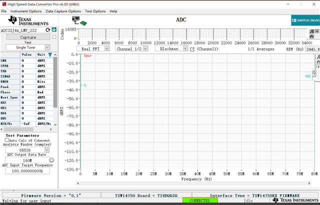
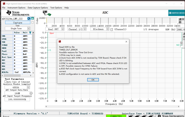
One customer used ADC32J25EVM and TSW14J50EVM to acquire data, he  followed the steps of the guide during the ADC32J25EVM and the TSW14J50EVM, but it reported TIMED OUT ERROR , could you please provide a detailed setup process? So that we can refer to it?

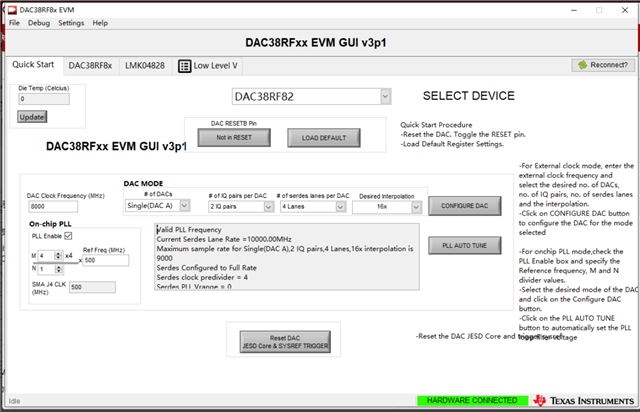
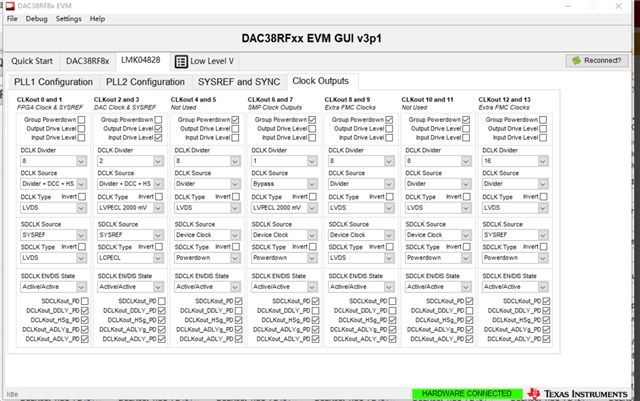
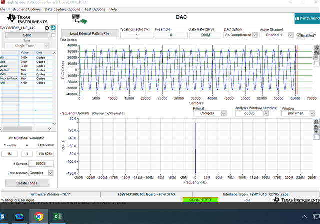
He also  used  the DAC38RF82EVM and the TSW14J10EVM, KC705 for the transmitter to complete a complete closed loop test with the ADC32J25EVM and the TSW14J50EVM. How should the transmitter be set?

Best regards

kailyn

  • Hi Kailyn,

    I am working on recreating a set up with the ADC32J25EVM and TSW14J50EVM and will get back to you once I have it. Thanks!

    Cheers,
    Fadi

  • Hi Kailyn,

    I was able to get the ADC up and running with the TSW14J50EVM by following the user guide instructions. Can you please help me understand the steps that were taken to reach the "TIMED OUT ERROR"?

    Additionally, for the DAC38RF82EVM, is the customer planning to use the TI IP? Otherwise, I would recommend reaching out to the FPGA vendor for support with the transmit IP. 

    Thanks!

    Cheers,

    Fadi

  • Hi Fadi,

    Thank you very much for your reply.

    Below is the customer's steps:

    1. Connected  DAC38RF82EVM with TSW14J10EVM、KC705

    2. 5V power supply for KC705 and DAC38RF82EVM, and connected DAC38RF82EVM and TSW14J10EVM to PC.

    3. Using 500Mhz crystal to J4 of DAC38RF82EVMt, J10 is open status.

    4. Open DAC GUI, setting the Quick start is as this:

    Click "config DAC".

    5. The  Clock outputs of LMK04828 is as this:

    6.Open HSDC Pro, ini files selected DAC38RF82_LMF_442。SPS changed to 500M。generated single-tone signal, the setting is as this:

    7.DAC GUI  click Reset DAC JESD Core & SYSREF TRIGGER

    8.Using SMA cable to connected DAC38RF82EVM J6 and ADC32J25EVM J3 。

    9.Connected ADC32J25EVM and TSW14J59EVM ,power supply and connected PC。

    10. Open ADC GUI,click Low level --->Load config,selected ADC3XJXX_160MSPS_LMK_Setting.cfg to load, and then we could find that  D2 and D4 of TSW14J50EVM are flash status.

    11. Open HSDC Pro, selected ADC32JXX_LMF_222.ini.to load and setting below cofiguration:


    Click"  capture", it appears error:

    Confirmed that D3 is off, D4 is flashing,

    These are all the processes that the customer did and eventually didn't capture properly. Ask for your help in identifying errors or missing steps during operation.

    Best regards

    kailyn

  • Hi Kailyn,

    For the ADC32J25EVM, can you please confirm which capture card is being used? You have mentioned both the TSW14J59EVM & TSW14J50EVM.

    Additionally, for the DAC38RF82EVM, is the customer planning to use the TI IP? Otherwise, I would recommend reaching out to the FPGA vendor for support with the transmit IP. 

    Thanks!

    Cheers,
    Fadi

  • Hello Fadi,

    Thank you very much for your reply.

    is the customer planning to use the TI IP?

    Yes, he would like to use TI IP.

    You have mentioned both the TSW14J59EVM & TSW14J50EVM.

    Sorry, he used TSW14J50EVM.

    Best regards

    Kailyn