- Ask a related questionWhat is a related question?A related question is a question created from another question. When the related question is created, it will be automatically linked to the original question.
Presentation for the problem for TI
We encounter a problem when sending a long burst of pulses on the AFE5818.
The problem is also the same with AFE5808.
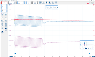
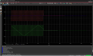
In the drawing above, we see the signals at the input of the System :
in blue : INP1, in Red : INM1 in Purple : difference of both.
The problem we encounter is due to the fact that the polarization offsets moves on the positive input and it takes time for INM and INP to go back to their initial level: during this time, we find dead zone (unusable for measurement) due to the amplification of the signal through LNA, VCAT, PGA. Even though there are Integrators/HPF in the LNA, PGA and ADC, the signal in the dead zone is not usable.
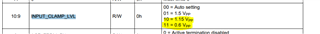
In one of our design, we decided to connect the ACT Pin and, in another design, ACT isn’t connected (floating input).
We tried to use the simulation model of the AFE5808 available on TI’s website, to reproduce the problem to tests different solutions
On channel 1 we tried the version recommended on the datasheets
On channel 4 the design as we implemented on one of our boards (I added a 100Meg Resistance to simulate a NC connection else the simulation doesn’t work)
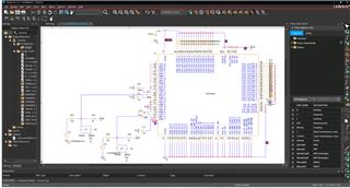
Trying to simulate the problem
On channel 1 :
OnChannel 4 :
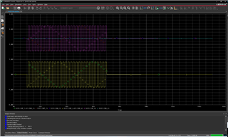
The simulation gives no difference with and without ACT capacitor, and in addition, the moving bias effect is not seen.
Is there something missing in my simulation? Or does the model not include this phenomenon? If so, could someone in TI fix the issue?
If the issue can’t be fixed, perhaps you’ve encountered this issue in the past? Is there a record of a possible solution?
Kind regards.