Hi team,
I am currently encountering challenges while attempting to continuously read data with the specified ADC. In my application, the device successfully performs measurements cycling with different inputs. However, during a specific event, I need to read a particular input continuously and sample at a specific rate (1k S/s). The issue I am facing is that every time this event occurs, I set the register to RDATAC mode, but the measurements returned consist of random values that are not related to the actual measurements I am trying to obtain.
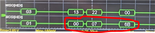
I captured some scope shots, and I observed that these unusual values are present in the MIMO bus. Therefore, they are not attributed to any form of noise in my communication system.
To enable RDATAC mode, I am configuring four registers and utilizing three commands. The registers include STATUS (enabling the input buffer), MUX (setting +AIN6 and -AIN7 as differential inputs), ADCON (for unity gain), and DRATE (for sampling at 2k S/s).
Attached is the scope shot for your reference.
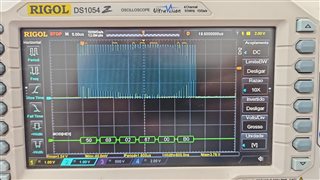
After writing these registers, a delay of 2ms is introduced. Subsequently, the commands RDATAC, SYNC, and WAKEUP are executed in this sequence, each separated by a 2ms delay.
After this initialization, I utilize the RDATA command whenever a DRDY (Pin) external event occurs, storing the returned values in a buffer with a size of 1000. Despite setting the DRATE for 2k S/s, I consistently receive one measurement every 1ms (strange behavior but not a problem).
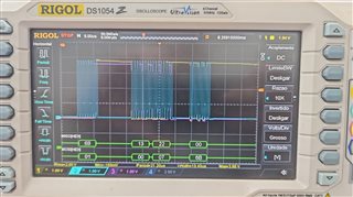
Here is a table displaying the returned values, along with the scope shot of the first measured value (Cap_Sample[0]).
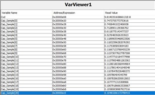
The expected measurement is a capacitive discharge (100nF in parallel with 1MOhm) with an initial value of approximately 0.156V.
Can you help me find what I am doing wrong?