Other Parts Discussed in Thread: ADS127L11
Hello TI Team,
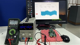
I have used ADS127L11 EVM with Teensy 4.0 ( MIMXRT1062DVL6B) Development Board.
Needful Setup in EVM : (ADS127L11EVM with an external controller board)
I have provide +5V to J12 at +Vin side and +2.5V to J13 IOVDD supply.
Jumper Connections:
Attached JP3 jumper. (as default)
Attached JP4 jumper with +Vin & +LDOVin pin.
Attached JP5 jumper with AVSS & GNS pin.
Attached JP6 jumper with 2&3 EVM Clk pin.
Attached JP7 jumper with 2&3 PHI Clk pin.
Connect RST,START,SDI,CS,SCLK,SDO and Ground pin with Teensy 4.0 SPI Interface.
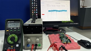
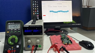
Also I here attached connection picture for the same.
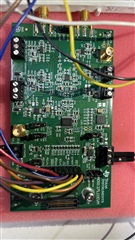
Please verify above connections and suggest if any changes required.
Firmware Development :
I will try to read and write register from ADS127L11 and also try with DEV_ID.
I make Start and Reset Pin High then try to send data in SDI.
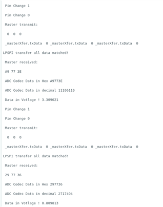
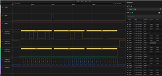
For getting 24 Bit ADC Raw data according to datasheet I have sent 0x00 0x00 0x00 (NOP) frame in SDI.
In that after sometimes I got RAW data in hex format and convert into codec format (5400662, 5400672,5399097 etc. Codec data). Also got 1.66V at J4 side.
I have check with change voltage at J4 side and got data in codec format but this changes is not instant it's take long time 2 to 5 minutes and also i din't get proper output voltage.
One thing also mention to here I didn't get this data continuously even though i have sent frame in SDI, unexpectedly at that time i got value 0x00. So, i need to set any other register from Firmware side?
Also i have observed when I power off Bench Power supply from +5V to J12 side and also +2.5V to J13 IOVDD supply side then i got same problem i got 0x00. So, Is there any Hardware side power sequence i need to follow to get RAW data?
I attached my .c & .h file for your reference.
/* -- driver library Includes -- */
#include "fsl_lpspi.h"
#include "fsl_gpio.h"
#include "fsl_debug_console.h"
#include "math.h"
/* -- Ended driver library Includes -- */

/* -- User defined library Includes -- */
#include "SPIWrapper.h"
#include "SystemDelay.h"
/* -- Ended User defined library Includes -- */

/* -- User defined variables -- */
static int32_t _errCode 				= kStatus_Fail;
static uint8_t _masterRxData[3] 		= {0U};
static uint8_t _masterTxData[4] 		= {0U};
/* -- Ended User defined variables -- */

void SW_LPSPI_Init(void)
{
	uint32_t _srcClock_Hz;
	lpspi_master_config_t _masterConfig;

   /*Master config*/
   LPSPI_MasterGetDefaultConfig(&_masterConfig);
   _masterConfig.baudRate = TRANSFER_BAUDRATE;
   _masterConfig.whichPcs = EXAMPLE_LPSPI_MASTER_PCS_FOR_INIT;
   _masterConfig.pcsToSckDelayInNanoSec        = 1000000000U / (_masterConfig.baudRate * 2U);
   _masterConfig.lastSckToPcsDelayInNanoSec    = 1000000000U / (_masterConfig.baudRate * 2U);
   _masterConfig.betweenTransferDelayInNanoSec = 1000000000U / (_masterConfig.baudRate * 2U);

   _srcClock_Hz = LPSPI_MASTER_CLK_FREQ;
   LPSPI_MasterInit(EXAMPLE_LPSPI_MASTER_BASEADDR, &_masterConfig, _srcClock_Hz);

   PRINTF("\r\n--- LPSPI Initialization Completed ---\r\n");
}

void SW_LPSPI_SetClockSource(void)
{
	PRINTF("LPSPI Set Clock Source\n");

    /*Set clock source for LPSPI*/
    CLOCK_SetMux(kCLOCK_LpspiMux, EXAMPLE_LPSPI_CLOCK_SOURCE_SELECT);
    CLOCK_SetDiv(kCLOCK_LpspiDiv, EXAMPLE_LPSPI_CLOCK_SOURCE_DIVIDER);
}


void SW_LPSPI_Write(void)
{
	uint32_t _index;
	lpspi_transfer_t _masterXfer;

	 memset(_masterTxData, 0, sizeof(_masterTxData));

   /*Start master transfer, transfer data to slave.*/
	_masterTxData[0]=0x00;
	_masterTxData[1]=0x00;
	_masterTxData[2]=0x00;
//	_masterTxData[3]=0x00;
//	_masterTxData[4]=0x00;
//	_masterTxData[5]=0x00;

   /* Print out transmit buffer */
   PRINTF("\r\n Master transmit:\r\n");
   for (_index = 0U; _index < TRANSFER_SIZE; _index++)
   {
       /* Print 16 numbers in a line */
       if ((_index & 0x0FU) == 0U)
       {
           PRINTF("\r\n");
       }
       PRINTF(" %02X", _masterTxData[_index]);
   }
   PRINTF("\r\n");

   _masterXfer.txData   = _masterTxData;
   _masterXfer.rxData   = NULL;
   _masterXfer.dataSize = 3;
   _masterXfer.configFlags =
   EXAMPLE_LPSPI_MASTER_PCS_FOR_TRANSFER | kLPSPI_MasterPcsContinuous | kLPSPI_MasterByteSwap;

   LPSPI_MasterTransferBlocking(EXAMPLE_LPSPI_MASTER_BASEADDR, &_masterXfer);

   /* Delay to wait slave is ready */
   if (SysTick_Config(SystemCoreClock / 1000U))
	{
		while (1)
		{
		}
	}
}

void SW_LPSPI_Read(void)
{
   uint32_t _errCount;
   uint32_t _index;
   lpspi_transfer_t _masterXfer;
   int32_t adc_val_raw = 0;
   float Voltage = 0;

   /* Start master transfer, receive data from slave */
   _masterXfer.txData   = NULL;
   _masterXfer.rxData   = _masterRxData;
   _masterXfer.dataSize = 3;
   _masterXfer.configFlags = EXAMPLE_LPSPI_MASTER_PCS_FOR_TRANSFER | kLPSPI_MasterPcsContinuous | kLPSPI_MasterByteSwap;

   LPSPI_MasterTransferBlocking(EXAMPLE_LPSPI_MASTER_BASEADDR, &_masterXfer);

   _errCount = 0U;
   for (_index = 0U; _index < TRANSFER_SIZE; _index++)
   {
       if (_masterTxData[_index] != _masterRxData[_index])
       {
           _errCount++;
       }
   }

   if (_errCount == 0U || _errCount != 0U)
   {
       PRINTF(" \r\nLPSPI transfer all data matched! \r\n");

       /* Print out receive buffer */
       PRINTF("\r\n Master received:\r\n");
       for (_index = 0U; _index < TRANSFER_SIZE; _index++)
       {
           /* Print 16 numbers in a line */
           if ((_index & 0x0FU) == 0U)
           {
               PRINTF("\r\n");
           }
           PRINTF(" %02X", _masterRxData[_index]);
       }
       PRINTF("\r\n");
   }
   else
   {
       PRINTF("\r\nError occurred in LPSPI transfer ! \r\n");
   }

   adc_val_raw = (_masterRxData[0]<<16)|(_masterRxData[1]<<8)|_masterRxData[2];

   PRINTF("\r\n ADC Codec Data in Hex %02X\r\n",adc_val_raw);
   PRINTF("\r\n ADC Codec Data in decimal %d\r\n",adc_val_raw);

   // Take Refrence voltage 2.5
   Voltage = (float)(adc_val_raw)*(0.000000298);

   PRINTF("\r\n Data in Votlage ! %f\r\n",Voltage);

}

void SW_GetSlaveData(void)
{
	uint32_t _loopCount = 1U;

#if LOOP_BACK_TEST
    PRINTF("LPSPI Start.\r\n");

	uint8_t _index;
    lpspi_transfer_t _masterSPI;
    uint8_t _masterRxData[LPSPI_TRANSFER_SIZE] = {0};
    uint8_t _masterTxData[LPSPI_TRANSFER_SIZE] = {0};

    for (_index = 0; _index < LPSPI_TRANSFER_SIZE; _index++)
    {
        _masterTxData[_index] = _index;
    }
    /*Start master transfer*/
    _masterSPI.txData      = _masterTxData;
    _masterSPI.rxData      = _masterRxData;
    _masterSPI.dataSize    = LPSPI_TRANSFER_SIZE;
    _masterSPI.configFlags = BOARD_LPSPI_PCS_FOR_TRANSFER | kLPSPI_MasterPcsContinuous;
    LPSPI_MasterTransferBlocking(BOARD_EEPROM_LPSPI_BASEADDR, &_masterSPI);

    /* Compare Tx and Rx data. */
    for (_index = 0; _index < LPSPI_TRANSFER_SIZE; _index++)
    {
        if (_masterTxData[_index] != _masterRxData[_index])
        {
            break;
        }
    }

    if (LPSPI_TRANSFER_SIZE == _index)
    {
        PRINTF("LPSPI loopback test pass!!!\r\n");
    }
    else
    {
        PRINTF("LPSPI loopback test fail!!!\r\n");
    }
#endif

    PRINTF("LPSPI Polling.\r\n");
    PRINTF("Master uses polling way and slave uses interrupt way. \r\n");
    PRINTF("Please make sure you make the correct line connection. Basically, the connection is: \r\n");
    PRINTF("LPSPI_master --  LPSPI_slave   \r\n");
    PRINTF("   CLK       --    CLK  \r\n");
    PRINTF("   PCS       --    PCS \r\n");
    PRINTF("   SOUT      --    SIN  \r\n");
    PRINTF("   SIN       --    SOUT \r\n");
    PRINTF("   GND       --    GND \r\n");

    GPIO_PinWrite(EXAMPLE_START_GPIO, EXAMPLE_START_GPIO_PIN, 1U);

    while (1)
    {
        /* Set up the transfer data */
        for (uint32_t _index = 0U; _index < TRANSFER_SIZE; _index++)
        {
            _masterRxData[_index] = 0U;
        }

        /*Start master transfer, transfer data to slave.*/
        SW_LPSPI_Write();

 		/* Delay 20 ms */
        SW_Delay_Ms(20U);

 		/* Start master transfer, receive data from slave */
 		SW_LPSPI_Read();

        /* Wait for press any key */
        PRINTF("\r\n Press any key to run again\r\n");
        GETCHAR();

        /* Increase loop count to change transmit buffer */
        _loopCount++;
    }
}
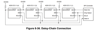
Once this problem solve also I need to Implement Daisy-chained.
Please help out to resolve this problem or provide guidance if i am doing any wrong direction.