This thread has been locked.

If you have a related question, please click the "Ask a related question" button in the top right corner. The newly created question will be automatically linked to this question.

ADS1174: Single Ended Input Review

Part Number: ADS1174
Other Parts Discussed in Thread: OPA1632, OPA1633, OPA350, REF3325, OPA2350

Hi,

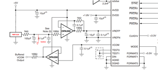
I have attached my current schematic for an ADS1174 circuit (based on the datasheet implementations) to acquire a single ended input signal with 0-2.9V range with my frequency of interest being 15kHz, but I have a few questions:

1. Is swapping the REF1004-2.5 (2.5 V reference) with a REF34-1.6 (1.6 V reference) the best way to change the FSR? Instead of (0-5V I want closer to 0-3V)

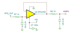
2. Is this interface also okay to use for the RTD or will it need a separate interface to read?

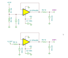
3. For these input interfaces should I change out the OPA1632 for OPA1633? It looks like the newer drop-in variant as OPA1632 is at end of life and might be more difficult to source soon.

Thank you!

ADS1174_830M1.pdf

  • Hello Braeden,

    Welcome to the TI E2E community.

    1.  Yes, in order to optimize the usable 16b of dynamic range of the ADS1174, using a 1.6V reference will be a better option.  You can also use a 2.5V reference and a simple voltage divider between the reference output and the OPA350 reference buffer to scale the voltage as needed.  You can then optimize your input range by adjusting the resistor divider ratio.  Below is Figure 26 from the datasheet modified to show using the REF3325 and a resistor divider.


    2.  No, for an RTD, you need a high input impedance.  I suggest using a simple OPA350 buffer between the RTD output and the ADC positive input, with the negative input connected to ground for this connection.

    3.  Since your sensor output is single ended, I suggest using a pseudo-diff input configuration, which does not require the fully differential input amplifiers, OPA1632.  Just using the OPA350 (or dual OPA2350), you can connect the negative input to the common mode output of your sensor (+3.3V/2), and use a simple buffer for the sensor output, as shown below.  Using a reference voltage of 1.5V and the below circuit, you can measure input voltages from 0.15V to 3.15V, 1.65V+/-1.5V.  You can also adjust the reference voltage to further optimize your full scale input range.

    For more information on different input type configurations, please take a look at TI Precision Labs, ADC input types.

    https://www.ti.com/content/dam/videos/external-videos/2/3816841626001/6279972316001.mp4/subassets/adcs-sar-adc-input-types-presentation-quiz.pdf

    The ADS1174 can be configured in any combination, including single-ended, pseudo-differential, and fully differential.

    Regards,
    Keith Nicholas
    Precision ADC Applications