This thread has been locked.

If you have a related question, please click the "Ask a related question" button in the top right corner. The newly created question will be automatically linked to this question.

DAC39RF10: DDS Mode switching time and SFDR clarifications

Part Number: DAC39RF10

Hi everyone,

I'm working with the DAC39RF10 and have a few questions regarding its performance:

  1. RF settling time: After the NCOs have been configured, what is the RF settling time of the DAC39RF10?
  2. Maximum frequency in NCO-only mode: What is the maximum frequency that the DAC39RF10 can generate in NCO-only mode?
  3. SFDR for a 500 MHz bandwidth: What is the SFDR specification for the entire frequency range (up to the Nyquist frequency) within a 500 MHz span? We are aiming for an SFDR better than -70 dBc in this frequency range.

Any insights or information on these questions would be greatly appreciated. Thank you!

  • Hello, 

    Unfortunately, each of these questions does not have a simple answer. If you provide your update rate I can give you some numbers, in particular for the second question. 


    1. The DAC has 12GHz of analog bandwidth, so the analog settling time is quite fast. In the digital domain, once the NCO is updated there is a digital latency until the NCO has time to update but this is in hundreds of clock cycles (very fast at fast update rates). The limiting factor will always be due to SPI or the Fast reconfiguration interface latency more than anything. 

    2. The NCOs use a frequency word that is normalized to FS/2. As with all DACs, frequency planning around Nyquist zones is necessary. You will always have an image in each Nyquist zone; however, the DES2XH output mode can help suppress the first Nyquist image and allow for some second Nyquist operation. The DAC's 12GHz analog bandwidth helps with this; however, you also must account for your output mode (NRZ, RTI, RTZ, DES2X) and its transfer function.  

    3. The only spurs you should see above 70dBc will be harmonics, (including folded harmonics). So again, this depends on update rate and generated frequency. 

    Regards, 

    Matt

  • Hi Matt,

    Thank you for your detailed explanation. For context, let's assume an update rate or Fclk of 10 GHz; the output mode is DES2XH.

    Given this configuration, could you please provide the following information:

    1. What would be the output operating frequency range for the DAC39RF10 in this configuration in NCO-only mode? (I mainly want clarity that the internal NCO can generate frequencies up to Fclk)
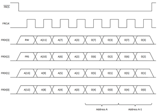
    2. Will the RF frequency hopping time, including the configuration of 64 bits of the NCO using the fast reconfiguration interface clocked at 200 MHz, come below 200 ns? 

    Any insights you can provide would be greatly appreciated.

    Regards,
    Krishnaprasad

  • Krishnaprasad, 

    Everything below assumes a 10GHz Fdac. 
    You would be able to synthesize up to 4GHz in DES2XL mode and 6-10GHz* (not including 10GHz) in DES2XH mode. Note that in DES2XH mode you still have 3rd Nyquist images to deal with, so in practice it would be less as a low pass filter would be needed to suppress the 3rd Nyquist image. Between 4 and 6GHz is not part of the passband of the DES2X interpolator so other output modes such as RTI and RTZ could be used, however you would still have the other Nyquist image to deal with. (5.5GHz tone would have a 4.5GHz image and vice versa). Its always a matter of Nyquist image planning as its historically always been with DACs.

    The good news is in DDS mode its actually quite easy to change the sample clock going to the DAC while its in operation, The DAC's frequency will change immediately when the new sample clock frequency is applied, meaning one could use 2 sample clocks (8Ghz and 12GHz for example) and toggle between them to get different "Nyquist holes" where frequency synthesis is either not possible or difficult. 

    As for the FR interface, 

    The datasheet specs 60ns of reconfiguration time for a 32 bit word. This is due to 4 clock cycles needed for the R/W bit along with address bits. Then 4 8bit registers writes (FR interface auto increments address), Each 8 bit word requires 2 clock cycles, meaning 8 additional clock cycles. A total of 12 clock cycles are needed to write the 32 bit word and therefore 12*5us (200MHz clock) = 60ns. 

    Extending this to a 64 bit frequency word update would require 8 8bit registers to be written, so 4 clock cycles + 16 clock cycles (2 per word) means a total of 20 clock cycles = 100ns. 

    If the DAC is configured for the FR CS~ to toggle the frequency word update, the device will update the frequency in the NCO very quickly once FR CS is pulled high (The interface is the dominating latency contributor). So 200ns is obtainable with an FR clock that's just a bit over 100MHz. 

    Regards,

    Matt