Hi,
Compilation environment: keil5
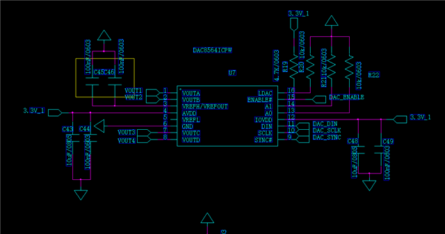
Using chip: DAC8564IDPW
1. Why is there a deviation in accuracy?
Control channel A to output a voltage of 2V (DIN instruction is 0X10CCCC). The multimeter measured the voltage of Vout A to GND as 2.060V, and the voltage of the other three channels was 0.092V
To individually control the output voltage of channel A to 0V (DIN command is 0X100000), the multimeter measured the voltage of Vout A to GND as 0.092V, and the voltage of the other three channels was also 0.092V
To individually control the output voltage of channel A to 1V (DIN instruction is 0X106666), a multimeter measured that the voltage of Vout A to GND is 1.075V, and the voltage of the other three channels is 0.092V
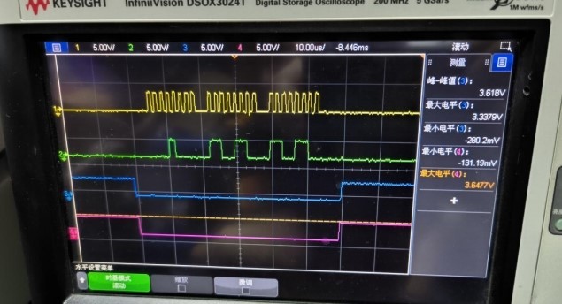
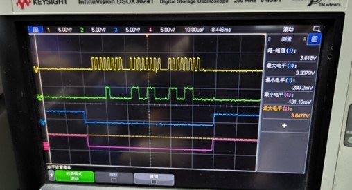
The following waveforms are sent to the DAC_DIN with a data of 0X10CCCC, and the four channels from top to bottom correspond to four waveforms: DAC_SCLK, DAC_DIN, DAC_SYNC, and DAC_ENABLE.
2. Why did the DIN send command change while maintaining the previous voltage value? How can I change the voltage output and shutdown of any channel in real time?


